Introduction
Human soldiers are the army’s most valuable resource. A lot of money is invested in their training. In order to minimise their exposure to risk, where possible they should be replaced with inexpensive robots. A good example is collecting intelligence at observation posts, where human soldiers tend to get tired and bored, and need a reliable supply of food, water and electrical energy (e.g. batteries or solar cells). Robots could also be used to support dismounted soldiers. In this application their mobility needs to– as far as possible –match that of a human soldier.
The Advantages of Robots. Robots can overcome most of the limitations experienced by conventional soldiers. Specifically, they can be equipped with an array of sensors that make their power of perception much superior to that of humans. They can also be equipped with artificial intelligence (AI) that can more rapidly analyse incoming information to assess the situation and forward this assessment to base. Robots can have five or more modes of communication. This enables them to operate in poor communications and GPS-denied environments. Further, they can operate autonomously (with no communication).
Further advantages of robots over human soldiers include the following:
- They can carry more than a human soldier.
- They do not require training.
- They just need data files and objectives.
- They can collect their own information and rapidly “learn on the job”.
- They can react much faster than humans.
- They can deduce the solutions to multiple problems simultaneously.
- They can deal with information overload by prioritisation and rapid deduction.
- They never get tired or bored.
A further advantage of robots is that they only need a supply of electrical energy. This would normally be supplied from batteries. For longer missions robots could recharge their batteries using solar cells, or liquid or gaseous fuel generators, or they could use fuel cells.
When considered in this way, the value of robots as a military capability is inescapable. Indeed, it raises the premise that the Australian Army should replace humans with robots wherever possible.
What Type of Robot Locomotion Should be Used?
Wheeled robots are much more energy efficient than limbed robots. Furthermore, they are much simpler and cheaper to manufacture. They can be assembled from Australian made electric motors, gearboxes and control systems that are used in the golf buggy market. They are therefore cheap and expendable. They could be transported as a flat pack. However, their mobility in difficult terrain is limited.
The limitations inherent in wheeled robots can be overcome by applying the principles of terramechanics to maximise their traction, energy efficiency and manoeuvrability. Traction is the ability for the robot not to become bogged when operating on difficult terrain such as slippery slopes or dense undergrowth. Energy efficiency is the ability to carry more kilograms more kilometres with less expenditure of energy. The energy source for robots is likely to be batteries. Therefore, a high energy efficiency will increase their range. Finally, manoeuvrability is the ability to rotate about any instant centre in the operating plane. This enables pure translation in any direction and pure rotation and anything in-between. This maximises the ability of the robot to navigate a path between obstacles.
The most effective way to maximise traction and energy efficiency is to invoke the principle of Cooperative Redundant Multiple Steering Systems (CRMSS). In this regard, there are basically two ways of steering a wheeled robot. One way is to steer (i.e. turn) one or more wheels. If we have N wheels, we will have N(N-1)/2 wheel-angle steering effects. Each steering effect is characterised by a theoretical instant centre (TIC). The other method is to positively and independently drive two or more wheels. Namely, if we have N’ positively driven wheels, we will have N’(N’-1)/2 wheel-speed steering effects. If we positively control all the wheel angles and speeds so that they produce N(N-1)/2 + N’(N’-1)/2 identical steering effects, they will all reinforce each other, and there will be no conflict between them.
Conversely, if the steering effects acting on the robot have different theoretical instant centres, they will fight one another to establish the actual instant centre. This is because a rigid body can only have one actual instant centre. This conflict will cause ground damage, tyre wear and increased energy consumption (note that the energy required to inflict ground damage and tyre wear comes from burning more fuel). A significant disadvantage of a robot with conflicting redundant steering systems is that it is kinematically indeterminate. This means its trajectory cannot be reliably calculated from its wheel speeds and angles.
In order to maximise manoeuvrability, it is necessary to be able to locate the single TIC of the robot anywhere in its operating plane. This maximum manoeuvrability can be achieved if all the wheels of the robot can be turned through an angle range of 180 degrees – providing the wheels can be rotated in both forward and reverse directions. In this way, the robot can crab steer in any direction (pure translation where the IC is at infinity in any direction). It can also rotate about its own centre (pure rotation) and any instant centre in its plane of operation. It is notable that, in conventional vehicles, translation requires some rotation and vice versa. This greatly reduces the manoeuvrability of these vehicles – and thereby their ability to avoid obstacles.
While Cooperative Redundant Multiple steering systems will generally maximise traction and energy efficiency, the following refinements should further increase traction:
Vertical wheel loads need to be equalised. Specifically, for any tyre/terrain couple there will be an optimum tyre pressure and vertical wheel load that will maximise the ratio of traction force to vertical wheel load. Therefore, the traction of the wheeled robot will be maximised if all wheels are subjected to the same optimum wheel load – assuming all tyres are identical. This ideal condition can be achieved by various means. Firstly, the payload should be distributed so that on level ground, all wheels carry the same vertical load. On uneven (twisted) ground, a load-equalising suspension is required to ensure that all wheels carry the same vertical load. On the traditional farm tractor, the vertical load on the drive wheels is equalised by mounting the front wheels on a beam axle that is free to rotate about the longitudinal axis of the tractor. If a robot has N wheels, it will require N-3 degrees of such rotational degrees of freedom, in order to equalise the wheel loads. Therefore for 4, 6 and 8 wheeled vehicles we require 1, 3 and 5 degrees of rotational freedom. Alternatively, we could use an active suspension system to as far as possible equalise the vertical wheel loads. Note that an independent sprung suspension cannot achieve load equalisation. It can approach this ideal with very long coil springs of very low stiffness.
Operating on slopes will tend to increase the wheel loads on the downhill wheels. This tendency can be countered by mounting the wheel assemblies at the end of swing arms that are attached to the body of the robot by hinges with a vertical axis. This will allow the wheel loads to be equalised by swinging both the downhill and uphill wheels further down the hill relative to the centre of gravity of the vehicle.
If the swing arms can also be rotated about a horizontal axis, the wheels can also be raised or lowered. This will allow the wheels to climb over or step over obstacles. If the bottom of the body of the robot was fitted with an upside-down treadmill belt or an upside-down walking floor the robot would be able to drag itself over obstacles.
Example of a 6WD/4WS robot
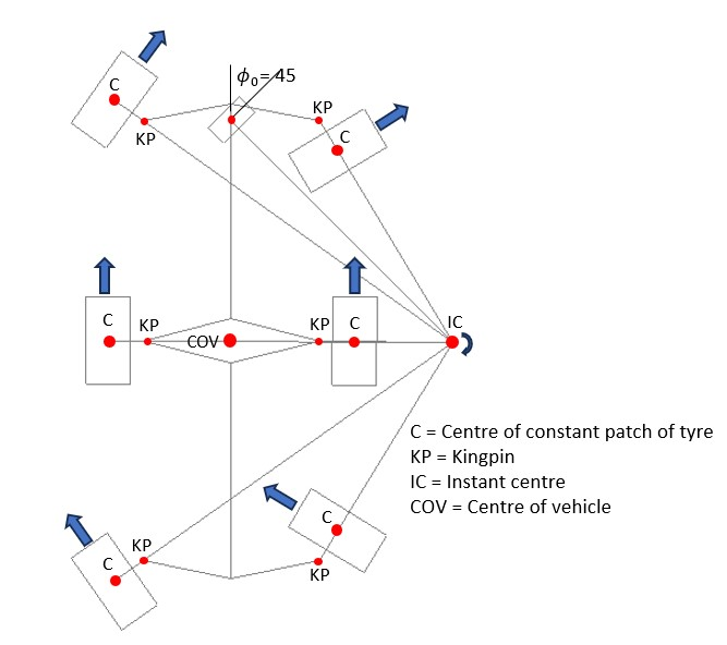
The following example illustrates how CRMSS can be applied to maximise mobility. Figure 1 shows a 6-wheeled robot in rotation mode where it can rotate about any instant centre located anywhere on the axis of the middle wheels. It can therefore rotate about its own centre if required. In this case the middle wheels are not steered. The location of the instant centre is determined by the angle ϕ0 of a notional (non-existent) wheel located midway between the front left and front right kingpins.
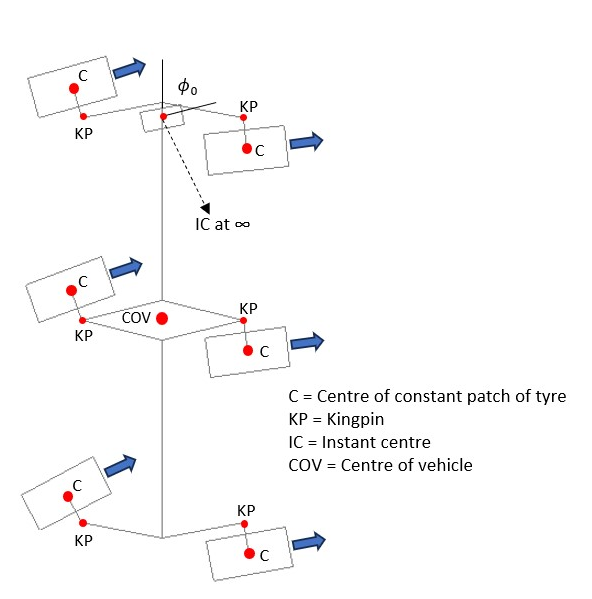
Figure 2 shows the robot in crab steer mode, where all wheels including the middle wheels are turned the same amount. In this case the location of the instant centre is determined by the angle of the notional wheel. Note that locating the contact patch of the tyres at least half the width of the tyres outboard of the kingpins makes it easier to accommodate a wheel angle range of 180 degrees. It also allows both top and bottom kingpins to be used to support the wheels.
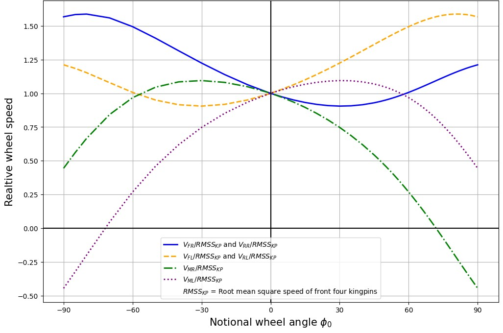
Figure 3 is a plot of the wheel speeds required to achieve the CRMSS effect. Note that for sharp turns, there is a large difference between the required speeds of the six wheels. When the instant centre is located between the contact patches of the middle wheels, one of the middle wheels must rotate in reverse.
Conclusion
Expendable wheeled robots can be used to reduce the risks to human soldiers. Although they will probably never match the agility of human soldiers, various novel terramechanical techniques can be used to maximise their operational envelope.
This article is a submission to the Spring Series 2023 Short Writing Competition, 'Army’s approach to accelerated preparedness'.
