QNG23 Challenge Outcomes
This post continues a series on quantum technologies. It details outcomes and findings from the Army Quantum Next Generation Minesweeper Challenge 2023.
Landmines and buried ordinances pose a significant danger in warzones, extending through active conflict and lingering as a threat in the aftermath. Finding and clearing landmines is both a valuable military capability and a humanitarian tool. Existing methods of minefield clearance are slow and dangerous, relying on ground teams and vehicles using active techniques to detect potential landmines.
Passively surveying minefields using magnetometers could be an additional tool to safely scan large tracts of land and provide clearance teams with targeted information on potential landmine positions. There is an immanent technology shift in the magnetometer market following the introduction of quantum-based sensors with atomic vapour cells, pushing these devices’ already impressive sensitivity limits to unprecedented levels [1].
The future of mine detection may look similar to the figure below, with a suspended magnetometer under a small drone capable of flying close to the ground. This sensor would detect minute changes in magnetic field strength and direction, enabling the identification of buried threats.
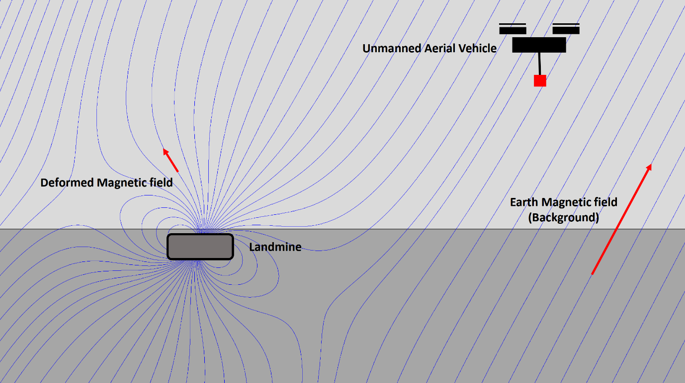
Figure 1: Demonstration of Earth’s magnetic field (blue lines), both undisturbed (Background) and deformed by metallic material in buried landmine (effect exaggerated for clarity). The field is sensed by a vector magnetometer (red box) hung beneath an unmanned aerial vehicle performing a grid scan of the area.
Detecting Landmines with Magnetometry.
Landmines are designed with three primary components: a structural body, explosive payload and trigger mechanism. The structural body can be manufactured from various materials, typically metals, ceramics, or plastics. Any mines with metallic components will have some innate magnetic signature, either as a permanent magnetisation generated by ferrous metals such as iron or an induced magnetism from non-ferrous metals.
For these induced magnetic fields, an external magnetic source is required to generate the magnetic signature of the landmine. Traditionally, magnetic signatures are detected with an actively generated magnetic source such as a metal detector. The primary magnetic field in most environments is earth’s innate magnetic field. This is a well-known effect, with the magnetic compass used as a north finding device for centuries. A compass acts as a rudimentary magnetometer, showing the direction of the local magnetic field.
Magnetometers detect mines by scanning for deviations in the earth’s magnetic field caused by the presence of magnetically alterable material used in the landmines construction (e.g stainless steel). This effect is very similar to using a magnetic compass near a large metallic object, where the needle is pulled away from the magnetic north by the local shift in the magnetic field created by the nearby metal. Sensing landmines in this way is an entirely passive technique that does not disturb the environment, and the mine cannot detect that it has been observed, removing the possibility of a detonate on detection type attack. An illustration of this magnetic effect is shown in Figure 1.
QNG Challenge
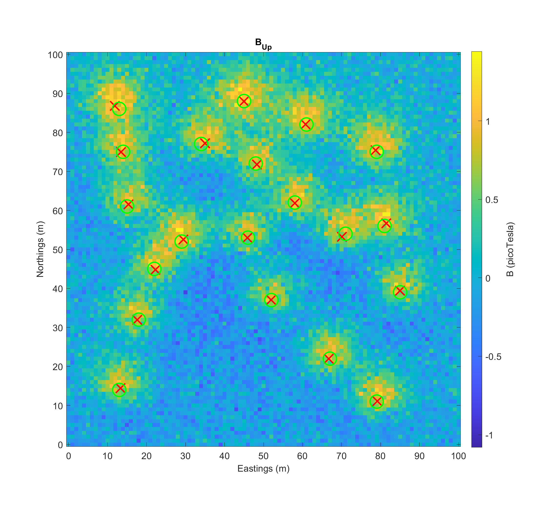
Army’s Quantum Technology Challenge 2023 tasked teams to find anti-vehicle landmines in a 100m × 100m flat minefield containing between 1 and 20 landmines. The mines were simulated as anti-tank mines containing 1.5 kg of non-ferrous stainless steel and buried just below surface level. Additional magnetic anomalies were distributed over the field buried to a depth of 30 metres and with a random magnetic direction and magnitude. These were used to represent magnetic signals from non-threatening sources (e.g. buried iron). Teams were given over 1000 scenarios of increasing complexity where a drone flown magnetometer surveyed the area at ten metres high with a one-metre interval measurement grid. Each scenario was simulated at a random location on earth’s surface with the expected local magnetic field applied to the area (World Magnetic Model 2020)[2]. A single example scenario is shown in Figure 2, including the magnetic anomaly signal, mine locations and position estimates from one of the competing teams for that scenario.
The threshold for successful detection was set as 0% false negative (no mines missed) to 10% false positive rate. Following this, the distance of the guessed mine positions from the true locations was calculated from the two dimensional Hausdorff distance (effectively, the greatest distance from an estimate to the true mine position).
In these scenarios, the highest performing team successfully identified the correct number of mines in 93% of trials, with the average largest distance from any mine identified being 1.3 metres from the actual target overall. Teams employed numerous techniques to process the magnetic field survey data to survey mine positions. The most successful teams used a matched filter based on a simulated dipole moment of the landmine from the local magnetic field.
At this altitude (10 m), the survey rate to produce an acceptable signal to noise ratio (SNR) was 0.1 square metre of survey area per second (27.8 hours for the full grid). Teams were allowed to adjust the survey pattern of the drone, which showed that the drone could be flown four times faster with a minimal decrease in effective landmine identification. This reduced the survey time of the entire area to 7 hours.
The landmine’s magnetic signal falls off as an inverse cubed effect. This means that as the sensor is flown closer to the mine, the anomaly signal can increase dramatically, reducing the survey time. Flying at a three-metre altitude increases the signal by a factor of 37. This shows a potential increase in survey rate to over 500 metres squared per second, giving a total scan time of less than 20 seconds for the entire 100m × 100m area. At this level, the magnetometer sensitivity is no longer the time-limiting factor; the drone’s maximum flight rate and dynamics are likely the primary limitations. A further dynamic system would involve a dynamic altitude scan, where the drone is flown over a wide grid at a higher altitude before lowering itself towards detected magnetic anomalies to pinpoint potential landmine positions. Such a capability would far outpace ground crew and vehicle mine detection and clearance rates.
Why Quantum Matters
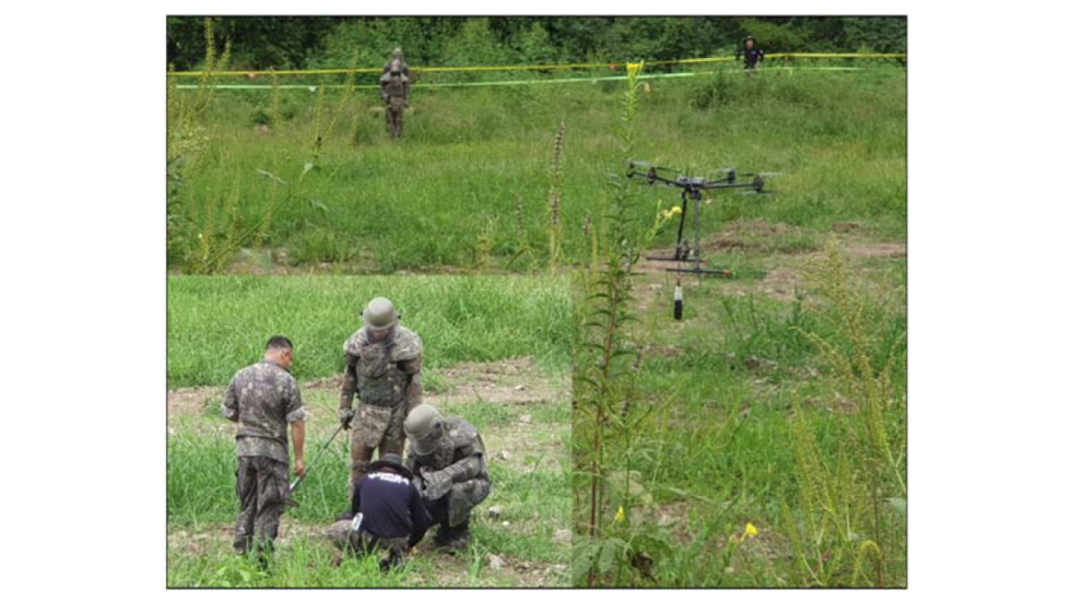
As described, magnetic anomaly detection is purely classical physics, and this methodology has already been demonstrated with existing classical magnetometers. The sensor noise used in the challenge simulation was based on a classical flux gate magnetometer. Figure 3 is from a research paper[3] where South Korean mine clearance teams used data from a drone flown classical sensor to investigate magnetic anomalies.
The sensitivity of current-day classical magnetometers sets an already impressive baseline measurement rate. Quantum magnetometers are beginning to reach commercial market availability, and the development of numerous quantum sensor technologies may push sensitivity limits to enable this capability further [1].
Implications and Next Steps
Quantum magnetometer technology has the potential to reduce the time it takes to conduct a route clearance and enhance minefield capability by providing every force element with a drone capable of performing scans and automated magnetic anomaly detection. In contested environments, having a drone capable of performing a rapid scan of potential routes and identifying the probability and potential positions of landmines would enable safer and faster decision-making for that single force unit.
Field experimentation to validate the magnitude of the magnetic signature from known landmines is the most pressing next step. These measurements could include platform integration of highly sensitive magnetometers to existing drone technology. Trials should be run in real-world simulated scenarios where the technology can be tested with additional magnetic anomalies and noise to test the technique’s robustness.
Endnotes
[1] Jiménez-Martínez, R., Knappe, S. (2017). Microfabricated Optically-Pumped Magnetometers. In: Grosz, A., Haji-Sheikh, M., Mukhopadhyay, S. (eds) High Sensitivity Magnetometers. Smart Sensors, Measurement and Instrumentation, vol 19. Springer, Cham.
https://doi.org/10.1007/978-3-319-34070-8_17
[2] NCEI Geomagnetic Modeling Team and British Geological Survey. 2019. World Magnetic Model 2020. NOAA National Centers for Environmental Information, 2020
https://doi.org/10.25921/11v3-da71
[3] Yoo L-S, Lee J-H, Lee Y-K, Jung S-K, Choi Y. Application of a Drone Magnetometer System to Military Mine Detection in the Demilitarized Zone. Sensors. 2021; 21(9):3175.
https://doi.org/10.3390/s21093175