
Agile Quantum Optimisation Algorithms for RAS Mission Planning
Authors: Shashank Sanjay Bhat, Udaya Parampalli, Joseph West and Tansu Alpcan
Executive Summary
Robotics and autonomous systems (RAS) are indispensable assets in modern warfare. The systems can perform critical roles such as logistics deliveries and reconnaissance. Current systems, however, are dependent on classical computing to complete decision-making processes. These classical systems often underperform in large-scale operations. Quantum computing, which leverages phenomena such as superposition and entanglement, provides a novel computational paradigm that can overcome such limitations. Among other benefits, it has the potential to enable military planners to optimise the achievement of RAS mission planning.
The integration of RAS and quantum computing has the potential to considerably improve military operational capabilities. Modern military operations require adaptable, precise and resilient decision-making capabilities. In multi-objective battlefield scenarios, these requirements can quickly exceed the classical computational capabilities of RAS systems. Acknowledging this limitation, this paper presents a computational framework to optimise the planning and efficiency of RAS-enabled operations based on an algorithm that is a hybrid between classical and quantum computing processes.
Global military institutions such as the Australian Defence Force (ADF), NATO and AUKUS have initiated strategic investments and experimental deployments of quantum-enabled technologies and autonomous systems. Australia’s Quantum Technology Roadmap highlights quantum-enabled capabilities as a strategic priority. The military potential of such capabilities was further emphasised by the use of Q-CTRL’s Fire Opal quantum-classical optimisation software during Exercise Talisman Sabre 2023. Under exercise conditions, Fire Opal showed significant reduction in the duration of the logistic deployments.
This paper presents the application of an algorithm called the quantum approximate optimisation algorithm (QAOA). The utility of the algorithm is considered through the lens of two vehicle routing problems (VRPs), one involving logistics resupply and the other dealing with reconnaissance. For logistics resupply, we used a hierarchical clustering strategy combined with quantum-enhanced optimisation methods to achieve the efficient allocation of supplies to a diverse fleet of remote autonomous vehicles. This method optimised payload utilisation and operational efficiency. Our experimentations demonstrate that complex routing problems involving up to 305 cities and 16 depots can be decomposed into smaller routing subproblems, with QAOA applied to selected subproblems of manageable size. The performance is evaluated using the average optimality gap across the QAOA solved clusters. For each cluster, the average optimality gap is calculated by comparing the QAOA solution for each cluster with its corresponding optimal classical solution, and taking an average across all the QAOA solved clusters. The metric shows the performance of the QAOA solved subproblems and does not represent the global optimality gap of the vehicle routing problem. For the purpose of this paper, the term ‘cities’ refers to operational nodes representing mission-relevant locations, including supply points, delivery destinations and named areas of interest (NAIs). Computation time remained under 5 minutes per scenario, demonstrating the practical utility of QAOA for military operations.
For reconnaissance, the framework was applied in a 3D environment, simulating realistic terrain, weather, risk and obstacle conditions. In the experiment, the hybrid framework assigned a fleet of aerial vehicles to prioritised reconnaissance tasks and determined optimal altitudes, with QAOA used for selected routing subproblems. In this scenario, sensor coverage and efficient routing within the manageable subproblems was achieved using quantum-enhanced optimisation. To measure performance, we used a quantitative evaluation method using two criteria: percentage coverage (alignment of achieved coverage with planned objectives), and percentage redundancy (measure of excess overlap). These metrics ensured that the intelligence value of the reconnaissance operation was maximised while resource expenditure was minimised.
In addition to providing the results of our experimentation, this paper addresses practical considerations in the use of agile quantum optimisation algorithms for RAS planning. It outlines the challenges involved in integrating quantum-enhanced systems into existing military infrastructure, emphasising the relevance of real-time ingestion of environmental and sensor data streams (such as lidar terrain models and weather reports). We also present critical cyber security considerations (such as data integrity assurance, secure encrypted channels, and robust authentication protocols) to align with the stringent military standards.
Throughout the paper, we stress the importance of maintaining a human-centric design system that has intuitive command interfaces, immediate visual feedback, and clear operational justifications. The reconnaissance-specific considerations include unmanned aerial vehicle (UAV) operational constraints, energy-aware mission planning and altitude-dependent sensor fidelity. Under the topic of system resilience, we also discuss fault injection testing and recovery from operational disruptions like GPS outages and communication failures.
From an international perspective, we consider NATO and EU initiatives such as QuantaQuest’s integrated quantum navigation systems and the concept of quantum key distribution (QKD), including their use in battlefield environments. Such initiatives would ensure that militaries can maintain operational superiority even when traditional infrastructure for communication and navigation is compromised. China’s ability to achieve successful intercontinental quantum communication shows the accelerated pace of global quantum technology competition. This development reinforces the necessity for allied nations to generate and deploy sovereign quantum capabilities.
Finally, the paper identifies several promising developments such as enhanced warm-start techniques for the QAOA, distributed quantum computing approaches and edge-deployed quantum processors that are capable of real-time operational adaptation. We give some weight to the need for modular quantum architecture that can enable incremental improvements to the current quantum systems without system-wide change. The paper also strongly recommends the establishment of transparent quantum decision-making processes; these are critical for maintaining command trust and operational accountability in quantum optimisation algorithms.
In summary, this work lays a foundational roadmap for integrating quantum algorithms into autonomous military systems. In doing so, it offers a clear and an actionable path towards achieving superior operational agility and computational advantage on the modern battlefield.
Introduction
Robotics and autonomous systems (RAS) include unmanned ground vehicles, aerial drones, and modular sensor systems.[1] These capabilities will be essential components in transforming how the Australian Army conducts missions such as logistics resupply and reconnaissance. The computational demands of these systems continue to rise, particularly in tasks that require evaluation of massive datasets under time and environmental constraints.
The convergence of RAS and quantum computing offers the Australian Army the opportunity to enhance autonomy, precision and adaptability, enabling mission-critical decisions to be made more quickly with a higher strategic impact. Quantum technologies offer a new paradigm, based on fundamentally different physical principles from those of classical electronics.[2] Further, quantum technology is being investigated as a potential approach for tackling combinatorial optimisation problems such as route planning and task allocation which are central to RAS mission planning.
This paper begins with a formal definition of RAS and quantum computing, including an overview of the relevant hardware and software components. The quantum approximate optimisation algorithm (QAOA) is then applied in case studies that involve two vehicle routing problems (VRPs), one involving logistics resupply and the other dealing with reconnaissance.
- QAOA is a hybrid classical-quantum optimisation framework designed to solve complex combinatorial optimisation problems by combining quantum computation with classical optimisation techniques. In this framework, quantum solvers are deployed for computational sub-problems of manageable size, typically at the cluster level, while classical methods handle problem decomposition, grid generation and fallback computation. Fallback computation becomes necessary in situations where quantum resources are unavailable, hardware noise levels are excessive, or quantum error rates lead to suboptimal or unreliable solutions.
- A VRP is an optimisation problem concerned with determining the most efficient routes for a fleet of vehicles to service a set of locations, subject to constraints such as capacity, distance, time, risk and resource availability. VRPs are a class of optimisation problem that is central to both military logistics and reconnaissance. Logistics resupply involves moving critical supplies such as ammunition, fuel, water and rations from depots to dispersed outposts while maximising fuel efficiency and minimising risk.[3] Reconnaissance involves gathering information from high-priority zones—often using unmanned aerial vehicles (UAVs)—where terrain, altitude, and sensor resolution play a big role. While they are well studied under classical computing, their scale and complexity can make exact classical optimisation computationally demanding, particularly when rapid replanning and environment modelling are required.[4]
While both logistics and reconnaissance VRPs involve RAS operating across a large mission space, each presents distinct operational challenges and computational structure. Often referred to as a variation of the travelling salesman problem (TSP),[5] both tasks are modelled using discrete spatial grids and dynamic environmental variables such as weather, terrain and risk exposure. As this paper demonstrates, QAOA[6] serves as an early proof of concept for quantum assisted RAS mission planning with a hybrid optimisation framework. Further advances in quantum hardware, solver reliability and system integration would be necessary before such quantum approaches can be considered for operational deployment.
Beyond the issue of algorithms, we address practical deployment concerns. Integration of quantum systems into real-world military infrastructure needs more than just computational efficiency. Real-time data ingestion from lidar scans—weather stations and vehicle telemetry—is also essential. Human–machine interfaces must allow military commanders to update priorities, drag the waypoints and receive real-time cost estimates. Fault tolerance is another priority—the system must handle GPS dropouts, unexpected obstacles or hardware failures in a graceful fashion, either by replanning or falling back to classical solvers.
The ADF has made notable investments in the field of quantum and autonomous systems through initiatives such as the Quantum Technology Challenge and collaborations with companies such as Q-CTRL.[7] Globally, NATO, AUKUS and other military alliances are also investing in quantum radar, quantum navigation and quantum secure communication.[8] As these concepts shift from prototype to deployment, the Australian Army must consider how to integrate them with autonomous platforms. By demonstrating scalable frameworks for both logistics and reconnaissance, this paper provides both a proof of concept and a roadmap for ADF decision-makers. The results show that hybrid classical-quantum frameworks can achieve rapid computation—even on commodity hardware. The QAOA architecture presented here is a compelling candidate for further experimental evaluation and progressively more realistic testing.
Overview of Robotic and Autonomous Systems and Quantum Computing (RAS-Quantum)
RAS is a rapidly evolving domain which encompasses unmanned ground vehicles (UGVs), aerial drones, autonomous maritime platforms, and sensor nodes (mobile and fixed).[9] These systems are designed to execute tasks by leveraging on-board computing, real-time sensor data and adaptive behaviour models with limited or no human intervention. Whether deployed for logistics resupply or reconnaissance, RAS enable operations in hazardous or inaccessible environments. Their deployment enhances critical factors such as persistence, precision and response speed.
RAS platforms integrate a wide array of components including perception systems such as lidar, thermal cameras, radar, navigation modules such as Global Navigation Satellite System (GNSS) and inertial systems, communication interfaces such as radio and satellite, and decision-making engines usually powered by classical AI. Autonomy levels vary as well, from remotely operated systems to fully autonomous agents capable of replanning and collaborative behaviour in multi-agent settings.[10] As the mission complexity scales up, classical pre-processing starts to have limitations. In areas of dense urban terrain, GPS-denied zones or environments where rapid, high-volume data processing is required, classical algorithms can begin to struggle. These challenges point to the need for advanced computational tools that can support the current architectures.
Quantum computing is being explored as a potential tool for addressing selected computational bottlenecks in the modern military setting. Unlike classical bits, which can be either 0 or 1, quantum computers rely on quantum bits (qubits), which exhibit properties such as superposition of the states and entanglement. These properties allow quantum systems to explore vast solution spaces, making them particularly useful in combinatorial optimisation, unstructured search, advanced cryptography and physical system simulation.[11] In the military context, quantum computing is being investigated for applications such as route optimisation, secure communication using quantum key distribution (QKD),[12] and sensing technologies for sub-terrain or GPS-denied environments. As the technology evolves, quantum computing is expected to be a foundational element of military platforms. Realising this potential is dependent on both the hardware that deals with the physical qubits and the software stacks that control and program these devices into operational systems.
Quantum Hardware
Quantum hardware is characterised by multiple competing technologies, each having its own approach to realising the qubits. The potential suitability of these platforms for military deployments depends on factors such as gate fidelity, coherence time, scalability, ruggedness, and environmental tolerance. While no universal quantum hardware has yet been developed, several leading technologies are detailed below.
- Superconducting qubits is probably one of the most mature and commercially available forms of quantum hardware. The qubits rely on superconducting circuits cooled using dilution refrigerators.[13] These systems offer fast gate speeds and straightforward fabrication using the current semiconductor infrastructure. However, their sensitivity to environmental noise makes them better suited for centralised facilities than for forward-deployed units.
- Ion trap qubits use electrically charged atoms or ions held in electromagnetic fields. They offer the highest qubit fidelity and longest coherence times of any architecture. This makes them suitable for high-precision operations. The trade-off comes with slower gate speeds and the need for high-vacuum systems and complex laser set-ups, which complicates field deployment.[14]
- Photonic qubits encode quantum information in individual photons. In contrast to ion trap qubits, these systems are well suited for quantum communication and QKD over long distances through fibre-optic channels. Also, unlike superconducting qubits, photonic systems have the advantage of operating at room temperature. There are, however, challenges in scaling up photonic qubits, due to the difficulty in creating strong photon–photon interaction[15]
- Spin qubits are often implemented in semiconductor materials (like silicon or diamond). They can be fabricated using existing microelectronic techniques and are often recognised for their potential in building scalable solid-state processors. Some spin-based systems can also function as highly sensitive sensors.[16]
As quantum hardware advances, the software infrastructure must also evolve in parallel. This includes low-level pulse control and error correction routines. Together, these layers are crucial for enabling reliable and adaptable quantum functionality.[17] The following section explores the software stacks which translate the emerging capabilities into practical applications.
Quantum Software
The software layer enables quantum systems to perform meaningful tasks and to interface with classical systems. The software ecosystem spans from low-level hardware control to high-level algorithm design and integration middleware. Every layer plays a critical role in ensuring that the quantum capabilities can be effectively leveraged with the given use case.
At the lowest level, quantum control software manages the timing and shapes the microwave, laser or optical pulses—essentially manipulating the individual qubits.[18] The control routines are sensitive to hardware-specific characteristics such as gate fidelity and noise profiles. In a military context, this layer would also include adaptive calibration routines that can maintain system performance. For instance, if a quantum processor is placed on a mobile ground platform, its control software must compensate for motion-induced noise.
The intermediate software layer consists of quantum compilers and schedulers that can translate high-level algorithms into hardware executable instructions. Tools like Qiskit and Cirq allow developers to write programs without worrying about the pulse level control.[19] [20] These platforms are critical for hardware agnosticism, enabling applications to switch between quantum back ends as needed.
At the highest level, quantum software interacts with classical computing infrastructure via middleware routines. This is a critical integration point for RAS. The middleware manages the hybrid workflows, allowing classical processors to offload a specific subroutine (such as optimisation, pattern recognition) to a quantum co-processor or a remote quantum node.[21] This layer also handles data formatting, compression and latency management, ensuring that information from the quantum sensors can be fed into real-time decision-making loops.
Robust software-defined quantum control is needed for systems to update or reconfigure dynamically in the field. For instance, a firmware update to a vehicle-mounted quantum sensor pod could enable it to switch from gravimetric sensing to magnetic anomaly detection depending on the requirements. Similarly, a quantum accelerator within a compute node could be reconfigured to perform cryptographic analysis from optimisation with minimal reprogramming effort.
When put together, these software layers provide the foundation for reliable, flexible and scalable deployment of quantum technologies. They ensure that quantum capabilities can be efficiently accessed, controlled and integrated with the broader architecture in place.
Quantum for RAS
Classical RAS systems can experience performance bottlenecks in dynamic situations requiring rapid decision-making, high precision and robust performance. Augmenting such systems with quantum technologies could help overcome these limitations. While it is not suggested that quantum technologies can yet replace classical systems, they can augment them in hybrid classical-quantum architectures. So, while core functions such as navigation and perception would still be performed by classical processors, quantum modules would be introduced (as a task-specific co-processor or as payloads) to accelerate certain functions. For instance, a quantum processor might handle route optimisation and return the results to the main control logic.
To enable such hybrid operations, a middleware layer would be essential. This interface would manage the exchange of data between classical and quantum subsystems. It would be responsible for converting sensor data into formats required for quantum processing and for routing outputs back into actionable commands. The middleware would also need to manage latencies, queue quantum jobs and ensure system-level synchronisation. For more demanding tasks, quantum computation could be offloaded to a remote quantum node via secure links.
This hybrid model would allow RAS platforms to benefit from the use of specialised quantum processing for selected computational tasks while retaining the dependability of classical systems. As quantum hardware becomes more mature, it may be possible to embed the quantum components more tightly within RAS platforms.
National and International Developments
Australia
The ADF has shown a clear strategic intent to integrate quantum technologies across its future capabilities, specifically in the land domain.[22] Through the Quantum Technology Roadmap, the Australian Army identifies targeted opportunities for quantum advances to achieve asymmetric advantages. Options range from improved navigation and secure communication to enhanced environment sensing.
In support of its strategic objectives, Army has instituted the Quantum Technology Challenge, an initiative to bridge from academia and industry into defence. This initiative aims to explore real-world applications such as quantum-enabled subterranean imaging, quantum-based optimisation algorithms for route planning and cryptographic resilience.[23]
A key demonstration of quantum-enhanced logistics occurred when the Army deployed Q-CTRL’s Fire Opal software for convoy optimisation during Exercise Talisman Sabre 2023. In the reported demonstration, Fire Opal reduced the total convoy deployment duration by approximately 10 per cent compared with the benchmark classic heuristic solver, ensuring all the convoys reached their destination before midnight. This was an improvement from the prior exercises, where some units arrived at 0100 h.[24] This trial shows the effectiveness of quantum optimisation in dynamic military environments.
In parallel, the Defence Science and Technology Group is pursuing quantum positioning, navigation and timing solutions (PNT). These systems are intended to operate in degraded environments, using quantum sensors to detect magnetic anomalies and to support autonomous vehicle navigation. A notable initiative has been the development of a ground-to-satellite optical quantum link. This is a positive step towards achieving secure quantum communication.[25]
Beyond these initiatives, the Australian Government is working through the AUKUS Pillar 2 framework to accelerate quantum research for military purposes. This framework brings together Australia, the United Kingdom and the United States to work on focus areas including quantum machine learning for sensor fusion and target classification, enhancing resilience in GPS-degraded battlespaces and developing better undersea detection systems. All these efforts aim to develop autonomous and semi-autonomous systems to operate in denied environments.[26]
In parallel to these government initiatives, Australian company QuantX Labs has developed Cryolock, a high-stability timing device with applications in radar and sensor networks. This technology is being used in collaboration with BAE Labs to enhance Australia’s radar coverage and tracking accuracy. This development has the potential to offer purer signal generation and to improve resilience against electronic interference.[27]
Worldwide
Beyond Australia, several military organisations are exploring quantum technologies in operational or near operational settings. NATO, for example, has identified quantum PNT and radar systems as areas of strategic focus. These systems would be critical in maintaining mobility and surveillance capabilities in environments where conventional systems may be compromised by jamming, spoofing or stealth technologies.
The QantaQuest initiative in Europe under the European Defence Agency is developing quantum navigation systems for mobile land units. These systems would enable movement in GNSS-denied theatres. The project has also demonstrated free-space QKD in urban environments to support secure communications in high-threat zones.[28] All these technologies are being positioned as key enablers of resilience in C4ISR (command, control, communications, computers, intelligence, surveillance and reconnaissance) under adversarial conditions.
China has also made significant investments in satellite-based quantum communication. An intercontinental QKD via the Micius satellite has been successfully demonstrated.[29] Reports indicate that China is also considering opportunities to integrate quantum sensing into early warning and counter stealth systems.[30]
Quantum RAS in Practice
This section explores two specific military applications for which quantum assisted algorithms may be applied: logistics resupply and reconnaissance. Both of these examples involve complex optimisation problems ranging from vehicle routing to path planning under environmental constraints. In this section we define the computational requirements and operational parameters of these problems. We also set the foundation for evaluating how quantum-enhanced solutions can be integrated into real-world defence scenarios using the QAOA.
Problem Definition
Modern military operations are characterised by their complexity and by the need for rapid decision-making in dynamic contexts. Be it coordinating ground convoys through harsh environments and remote regions or deploying unmanned systems for surveillance, efficient route planning is the key for mission success. The VRP has become the foundational framework for modelling these scenarios. The VRP extends the TSP by having multiple vehicles with capacity constraints servicing multiple cities and multiple depots.[31]
As outlined in the introduction, logistics resupply and reconnaissance each present a unique set of challenges. This section presents a detailed examination of these mission types and the challenges they impose on military planners. By detailing separate problem formulations for both logistics resupply and reconnaissance, we demonstrate how the proposed mathematical modelling framework can be applied across distinct operational contexts. We also emphasise the need for adaptability, driven by the dynamic nature of military environments and evolving requirements of the battle space.
Problem Formulation for Logistics Resupply
In military logistics, resupply operations involve ground convoys or assets moving between a brigade and multiple battalions. In this context, military planners have to consider the following issues:
- Which vehicle carries the supplies?
- How are the supplies distributed at every stop?
- What routes are to be followed to minimise risk and travel time?
Every military formation presents a unique supply demand, and RAS come with storage limitations, defined payload capacities and operational constraints. Beyond the simple routing factors such as road quality, weather effects and the risk of enemy ambush, they introduce additional constraints that increase the complexity of the optimisation problem.[32] This makes military resupply efforts more complex than civilian logistics.
Core Problem Elements
A military logistics resupply problem can be mathematically modelled as a specialised VRP. Some of the core components of a VRP model are:
- Supply demand at the customer nodes. Each resupply point has a specific logistical demand. These demands can be further subdivided into two tiers:
- Priority demands. These are critical resources which must be delivered promptly. They are essential for operational continuity. They primarily comprise ammunition, water and fuel.
- Operational demands. These are the additional supplies necessary for sustained operations. They will include rations and other support items.
- Vehicle capacity and constraints. Every vehicle in the fleet has a maximum carrying capacity. The vehicles also have a fuel capacity, speed capabilities and maintenance intervals. These factors will decide how efficiently a vehicle can travel without performance degradation.
- Travel cost and penalties. In a VRP, the goal is to minimise the cost function. The term ‘cost function’ refers to the mathematical expression used for quantifying the total operational cost of a routing solution, which includes factors such as travel distance, fuel consumption, risk exposure, payload utilisation and constraint violation. Assessing the cost function involves consideration of the following variables:
- Travel distance/time. Total distance covered by every vehicle, a factor which correlates with fuel consumption and schedule.
- Risk exposure. Routes that pass through high-risk zones are penalised in the cost function.
- Capacity violation. If a specific route assigned to a vehicle would demand more supplies, then a heavy penalty is imposed.
- Time window constraints. Some nodes would have specific time delivery windows. While these are usually imposed as hard constraints, soft constraints would allow slight deviations at an increased cost.
- Adaptability and dynamic updates. Operational conditions are rarely static; new intelligence can necessitate a rapid re-optimisation of routes. The supply chain must therefore be adaptable enough to quickly re-solve the VRP under such dynamic conditions.[33]
Field Scenario
Imagine a scenario in Northern Australia where a central logistics depot is responsible for supplying dispersed ADF units operating across remote and underdeveloped transport networks following disruption to critical port infrastructure. The operational environment is challenging, roads are limited, terrain conditions vary significantly, and weather events can rapidly affect route accessibility. In a contested environment, the risk of surveillance, disruption, or hostile interference with supply convoys must also be considered.[34] Mission-critical supplies such as ammunition, water, fuel, and rations must be delivered efficiently to sustain ongoing operations.
A tailored VRP algorithm could be used to optimise the delivery of military logistics in this scenario. The model would integrate multiple factors, including:
- Demand at every base. Every base would require a mix of supplies such as ammunition, water and rations to function effectively. In the VRP model, these demands are treated as hard constraints, meaning that each base must receive at least the minimum quantity of each supply type at minimum defined levels.
- Vehicle capacity constraints. The VRP model presupposes that a fleet of vehicles is available with different specifications. They may range from fuel tankers to multi-supply trucks. The model accounts for the differences in vehicle capacities to ensure that each vehicle operates within its operational limits.
- Road network costs. Given the harsh and dynamic operating environment, the routes to a specific battalion can undergo changes in real time. The VRP model therefore calculates the travel costs and penalties based on the variables outlined in the previous section.[35] For instance, a route passing near an enemy observation post would incur a high risk cost.
By integrating these factors, the VRP algorithm can offer RAS military planners a systematic method to generate resupply routes that balance efficiency, safety and effectiveness. For example, if new intelligence were to reveal that a specific segment of a planned route was compromised (due either to increased enemy activity or to environmental degradation), the VRP model could be re-executed with the updated inputs. This re-optimisation process would generate alternative plans that continue to minimise the cost function and ensure that logistics resupply is achieved at all necessary unit levels.[36]
Problem Formulation for Reconnaissance
Reconnaissance missions focus on gathering intelligence from key points in a remote or a contested area. Such missions seek to minimise risk and time while maximising the collection of critical sensor data such as imagery, signals and electronic surveillance.[37] The challenge here is to design routes for unmanned vehicles that cover all the designated observation points while keeping constraints such as battery life, flight time, exposure to enemy detection and sensor operational parameters in check.
Core Problem Elements
The core problem elements for a reconnaissance problem include:
- Intelligence gathering points. Each of the target locations is selected for a strategic value. Each of these points also comes with a dwell time and sensor resolution. In combination with sensor resolution, dwell time ensures that the platform captures enough data to make informed decisions.
- Vehicle performance and autonomy. Reconnaissance vehicles are subject to considerable operational constraints. For instance, drones may have limited battery life and must return to the base station before depletion. The performance of the vehicles is a function of fuel or battery capacity, speed, altitude and risk factors.
- Travel cost with risk exposure. Since reconnaissance missions are conducted in contested environments, exposure to adversaries can change the problem outcome. The specific altitudes required for a given sensor resolution may also restrict usable paths, adding further complexity to the problem.[38]
Field Scenario
Imagine a defined NAI at a known location. The entire NAI has been classified into three regions: high-priority, medium-priority and low-priority zones.[39] A UAV is tasked with swiftly gathering imagery from observation points spread across the NAI. Each observation point is classified according to its priority and sensor resolution.
The planning challenge is formulated as a VRP where the objective is to maximise the coverage of the designated points from the given fleet of UAVs while minimising the total flight time, energy consumption and risk exposure. Constraints here would include battery or fuel limitations.
In this scenario, a single designated UAV might be tasked with (for example) covering three high-priority points, two medium-priority points and one low-priority point. The VRP model calculates a route which minimises the constraints while maximising the coverage for these specific points. Since the environment is dynamic and subject to frequent change, variations in factors such as risk, weather or altitude would require the solver to recalculate the optimisation problem and generate an updated UAV route accordingly.
Challenges in Implementing VRP-Based Systems
Regardless of whether a VRP relates to logistics resupply or reconnaissance, there are some common challenges. These include:
- Computational complexity. The number of routes, the number of depots and the number of vehicles all influence the total number of possible outcomes. This makes finding the optimal solution difficult, especially when there are multiple constraints involved. Approximation algorithms and heuristics are typically used.
- Dynamic environments. Since the operational environments are invariably dynamic, an optimal VRP solution at one stage can become outdated due to changes in weather, enemy activity and other factors. Rapid re-optimisation capabilities are crucial in such scenarios. It is also necessary that the system not only generates a solution but also updates it in real time.
- Multi-objective optimisation. The cost function for a military setting is typically multi-objective. It combines variables such as minimising travel distance, reducing exposure to risk and ensuring timely delivery. Determining the relative weight to apportion to these factors is another challenge.
- Data quality and availability. Effectively resolving a VRP relies on accurate and reliable data. In an operational setting, the data can be incomplete or uncertain. Algorithms must be resilient in the face of noisy data and incomplete information.
A major unifying theme for both these problems is the need for rapid adaptability. Modular design and robust data inputs are characteristics of a VRP model that allows for continuous improvement in operational planning.
RAS-Quantum Use Case Implementation
This section uses the case studies of logistics resupply and reconnaissance to show how quantum algorithms—and specifically the QAOA—can be used to solve VRPs. Through our experimentation, we show that a hybrid quantum system can effectively solve clustered subproblems derived from a real world VRP with the limited qubit constraints imposed by the current hardware.[40]
Methodology
We applied the same modular and scalable system architecture for both the logistics resupply and reconnaissance experiments. For logistics resupply the environment was modelled as a 2D grid with terrain, weather and risk fields. Depots and outposts were randomly placed and vehicle classifications assigned fuel limits, payload capacities and maintenance schedules. A hierarchical clustering algorithm grouped the delivery points into feasible clusters, each of which became an optimisation problem. For reconnaissance, the simulations extended into 3D, considering the altitude of UAVs. Sensor resolution and field of view determined the optimal altitude for each mission point, and the system computed effective ground coverage using conical projection models.
For both the cases, the model was informed by the geometric distance and also by the traversal cost maps. Traversal cost maps were constructed using a weighted combination of weather intensity, terrain and risk, and wind directionality. This cost map then guided an A* pathfinding algorithm[41] in order to determine the safest and most efficient routes between the nodes. The results were then fed into a QAOA or a Held-Karp solver[42] depending on the cluster size.
In both cases, we defined appropriate evaluation criteria. For logistics resupply, we used the average optimality gap (which is the average percentage deviation of the QAOA solution from the optimal classic solution for each of the QAOA solved cluster. The average optimality gap is not the same as the global optimality gap of the routing problem considered) with the computational run time. For the reconnaissance task, the metrics included percentage ground coverage (how well the planned zones were scanned) and redundancy rate (how often zones were covered multiple times). The metrics delivered calculated and stored data frames, enabling clear and competitive analysis across scenarios.
Logistic Resupply
A full quantum solution to the logistics resupply VRP is not yet achievable; hardware is not yet mature enough to take over the classical systems and there is limited qubit availability.[43] However, using K-means we were able to systematically deconstruct the VRP via a process known as hierarchical clustering. This process uses an A* search to find the most effective route to the destination, and the QAOA for the TSP subcomponent. The QAOA component is formulated as a quadratic unconstrained binary optimisation (QUBO) problem that is fed into the quantum computer.[44] Below, we elaborate every implementation module, highlighting their interplay.
Problem Deconstruction
The first step was to systematically deconstruct the routing problem into solvable components:
- Hierarchical clustering (top down). This is the initial clustering step which reduces the problem complexity.[45]
- Environmental simulation. Realistic environment constraints for terrain, weather and risk are mapped to a discretised grid.
- Battalion demand. Every battalion is assigned a two-tier demand priority (i.e., critical and operational).
- Vehicle fleet definition. Diverse vehicle types with unique capacities and constraints are specified.
- Dynamic cost evaluation. Paths are computed considering the environment factors and operational constraints.
- Quantum classical solver. Solves the clustered nodes using either QAOA or a classical subroutine.
- Fuel aware segmentation. Routes assigned are divided into realistic operational legs based on fuel constraints.
Hierarchical Clustering (Top-Down Partitioning)
To address the complexity of routing and resupplying hundreds of nodes, this framework adopts a hierarchical top-down clustering approach. Rather than solving the massive routing problem in a single pass, the system breaks it down to smaller and more manageable components.
The process begins with the initial clustering of all the nodes using the K-means algorithm. Consider a hypothetical scenario where we have 750 nodes to resupply. The number of nodes per cluster is chosen so that each of the clusters gets a more manageable number of cities. This ensures that each cluster is more quickly and independently executed.[46]
Following the initial clustering, capacity constraints are enforced. Every cluster is evaluated to determine if the total demand of the cities exceeds the payload capacity of a given vehicle. If it does, then the node with the highest demand is removed from the cluster and assigned to a new one. This rebalancing is carried out until every cluster complies with the vehicle’s operational limits. At the end of rebalancing, every cluster can be serviced by at least one vehicle from the fleet without the need for rerouting.
Once the clusters are capacity feasible, another local rebalancing step is performed. Here the system examines if any node in a specific cluster can be economically assigned to a neighbouring cluster. If transferring the node would reduce the estimated round trip, then reassignment occurs. This ensures that the nodes are clustered not just by proximity but also by route efficiency, reducing travel distance, fuel usage and delivery time.
Through this systematic partitioning, the initial problem—which may have seemed too large and unsolvable—is now transformed into well-balanced and efficient clusters. Each of these clusters can be solved independently via either classical heuristics or QAOA.[47]
Environmental Modelling and Grid Resolution
The theatre of operations for this task was modelled as a 2D grid measuring 100 x 100 units. To enable efficient computation, the complete grid was discretised into square cells based on the user-defined resolution.[48] Each cell would represent a distinct geographic path within the operational area. Achieving a higher resolution provides smaller cells and more detailed representation but imposes a higher computational cost. Conversely, lower resolutions enable faster computation but may be insufficiently detailed to support optimal routing decisions.
At a selected resolution, the system generates three environment layers that influence the vehicle performance and route planning. The first is the terrain layer, which simulates the natural topographical variation. The terrain layer directly impacts ground vehicle behaviour by modifying speed and fuel consumption depending on the slope and elevation profile.[49]
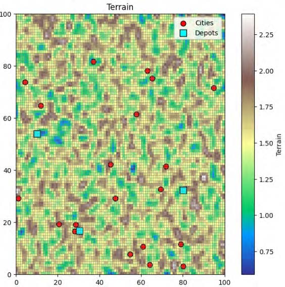
The second layer is the weather intensity, which is assigned a value from 10 to 30. Every cell in the grid represents the severity of the weather, with higher values indicating more adverse conditions such as storms or reduced visibility. These conditions degrade vehicle performance, increasing travel time and fuel consumption.
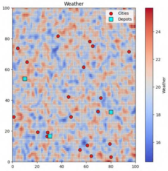
Darker shades represent more extreme weather.
The third layer represents risk, which is normalised on a 0 to 1 scale. This layer captures operational hazards such as potential ambush zones or natural dangers such as landslides or flooding. Cells with higher risk value incur higher traversal costs and may be completely avoided during the path planning process.[50]
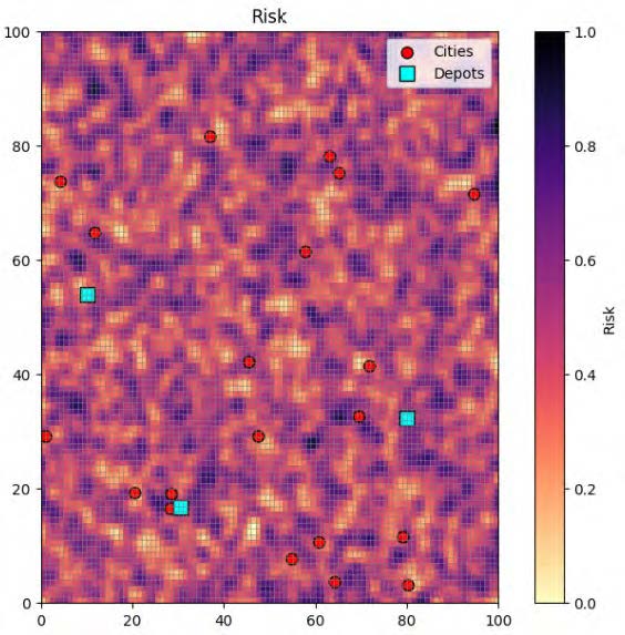
Darker shades represent more risk.
The three layers are combined into a universal traversal cost map where each cell holds a scalar cost value showing the complete difficulty. The result is a richer simulated operational environment where the routes are planned not just by distance but also by the environmental impact. The chosen resolution governs the fidelity of the model.
Node and Depot Placement on Grid Resolution
In this framework, depots represent locations where the supplies are stored, while nodes or cities represent locations that require resupply. Both depots and nodes are assigned to discrete cells. Each depot and node is allocated exactly one cell, ensuring unambiguous positioning within the environment. Typically, the assignment is performed on a highest available resolution, preserving the fine-grained spatial accuracy and allowing the simulation to capture the complete influence of the cost factors.
By allocating these locations to individual grid cells, the model ensures that every route begins and ends with a unique environmental characteristic. This feature introduces realistic variability to the routing conditions, reflecting how conditions near nodes or depots can alter the travel time and fuel usage.
The random assignment of the depots and nodes further contributes to the model’s realism and generalisability. In a real-world scenario, the precise locations of supply points and destinations are unpredictable and distributed.
Battalion Demand Modelling
Every battalion in this framework is assigned a set of resupply requirements categorised into two priority tiers. This dual-tiered demand model ensures that the optimisation process distinguishes between mission-critical and secondary resources.
The first tier consists of priority demands. The model enforces strict constraints on these items. A failure to deliver them in full triggers severe penalties in the optimisation process. This mimics the urgency of the real-life mission-critical supply chains, where delays can be expensive.
The second tier comprises operational demands. Although they are treated with lower urgency, these demands must be met to maintain troop endurance and long-term mission effectiveness.
By having a two-tier approach, the optimisation algorithm prioritises deliveries, ensuring that the essential resources are delivered first while managing the broader logistical goals.
Vehicle Fleet Specification
The vehicle fleet consists of a diverse set of vehicles, each designed with realistic operational constraints and performance characteristics. The set of vehicles reflects the variability found in the Australian Army’s military fleet, allowing the simulation to capture a broad range of delivery strategies.
Every vehicle is defined by its resource-specific payload capacities for ammunition, water, fuel and rations. For instance, lighter tactical vehicles such as the Hawkei may prioritise speed and manoeuvrability but carry less total weight. By contrast, heavier transport vehicles such as MAN HX77 are designed to move large quantities of supplies but are sensitive to variables such as terrain and fuel consumption.
Beyond the payload and fuel constraints, vehicles are also assigned maintenance parameters. Every vehicle has a maintenance interval which is defined in terms of either time or distance. The maintenance parameter ensures that route planning considers not only where the vehicle can go but also how long it can stay operational without performance degradation.[51]
Additionally, every vehicle is assigned a nominal speed, representing its optimal travel velocity under ideal conditions. To account for the variability in the environment, the model incorporates sensitivity factors that change the speed according to three key influences: weather intensity, terrain roughness and operational risk levels. As vehicles traverse cells with adverse conditions, the effective speed reduces in proportion to these parameters, reflecting real-world delays and hazards.[52]
The optimisation algorithm selects the most appropriate vehicle type for every cluster, matching delivery requirements with vehicle capabilities. This matching improves the feasibility and effectiveness of the mission planning.[53]
Dynamic Cost Evaluation
The route cost estimation is performed by the A* algorithm which operates over this discretised grid.[54] Vehicles traverse the grid by moving between axially adjacent cells. This movement supports the controlled path exploration, avoiding unrealistic shortcuts such as diagonal traversal or terrain-blind routing.
The algorithm performs adaptive cost accumulation across each cell in the vehicle’s potential path. The accumulated cost includes not only the Euclidean distance between the cells but also the dynamically computed values for fuel consumption and travel time. These are influenced by both the vehicle’s internal state (such as remaining fuel, mechanical health and maintenance status) and external environmental conditions. For instance, routes that pass through areas of high elevation, extreme weather and high risk accumulate higher costs.
The system employs path caching to significantly improve computational performance during large-scale optimisation phases. Once a path between a pair of cells is calculated, it is stored in the cache for further reuse.
This caching approach avoids recomputing pairwise paths that are reused across multiple candidate tours.[55]
The combination of A* pathfinding with caching and detailed environmental simulation achieves realistic and accurate costs that reflect real-world constraints.
Quantum TSP Solver
The optimal route calculation within the clusters happens via a hybrid quantum-classical optimisation strategy. For clusters ranging from two to four cities, the system uses the QAOA to determine the optimal route sequence. The strategy uses precomputed and cached pairwise path costs to compute the total cost of each candidate sequence.
The cluster-level routing task is first formulated as a QUBO problem. This encoding captures both the objective function and constraints (such as the requirement that no city gets revisited) in a binary variable representation. For a cluster with n nodes the QUBO model requires n^2 binary variables to represent the tour sequence.[56] So a four-city routing problem translates into a 16 qubit QUBO formulation.
The QUBO matrix is then transformed into an equivalent Ising Hamiltonian. This Ising Hamiltonian is compatible with quantum hardware back ends such as superconducting qubit systems.[57] The QUBO matrix is compatible with annealer-based systems. The Ising model interprets the cost function in terms of spin interactions.
The current implementation maintains the solution quality and valid route recovery remain acceptable for clusters up to four cities. Practical experiments have demonstrated that, where QAOA is applied beyond five nodes, the solution space becomes increasingly saturated with invalid routing sequences. So the application of the QAOA on larger clusters is limited under current hardware conditions.
For larger clusters, the system uses the Held Karp algorithm where tractable; otherwise, the system further partitions the larger cluster into smaller, computationally manageable sub clusters, which are then solved using the Held Karp algorithm..[58] The resulting optimal (or near-optimal) routes between sub-cluster centroids then form a higher-level routing problem.
When quantum resources are available, the system solves the smaller clusters using the QAOA. If the quantum resources are not available, then the system reverts to the classical approach to provide an exact solution for the corresponding tractable TSP subproblem. By selectively deploying quantum optimisation for small clusters and using classical enumeration for the others, the system maintains a balance between speed and quality. The scalability of the overall framework is primarily enabled by the hierarchical problem decomposition.
Vehicle Selection per Cluster
Vehicle assignment is another critical step in ensuring that the logistics resupply plan is feasible and cost-effective. This process evaluates the available vehicle fleet against the requirements of every cluster.[59]
First, the payload capacity of every vehicle is assessed relative to the total demand of the cluster. A candidate vehicle must be able to carry the complete set of assigned supplies—including both priority demands and operational demands. If the cluster’s demand surpasses the capacity of the single vehicle, then re-clustering or reassignment is executed.
Second, the system also checks the vehicle’s operational range. Using the precomputed traversal costs, the algorithm estimates the total cost of the planned trip and ensures that a vehicle can complete it within its fuel and maintenance limits.
Finally, among all viable options the algorithm selects the vehicle that offers the lowest total operational cost for the specific cluster. Again, the total travel cost estimation will rely on the precomputed route data and will include all of the relevant penalties.
This assignment routine ensures that each cluster is serviced by the most suitable vehicle type. In doing so, this approach maximises delivery reliability while minimising resource usage.
Fuel-Aware Route Segmentation
Once the optimal routes are generated for every vehicle, the system performs a fuel-aware segmentation process to transform the delivery sequence into realistic operational legs. Each operational leg begins and ends with a depot and represents a complete trip that a given vehicle can execute without the need for mid-route refuelling. As the vehicle visits the cities along the assigned route, the system tracks the fuel usage. When the estimated fuel usage exceeds the vehicle’s available fuel reserve, the system inserts a return leg to the depot and initiates a new leg for the remaining cities.[60]
For instance, if a vehicle is assigned to visit six cities, it may be required to split its mission into two separate legs:
Depot → City 22 → City 80 → Depot || Depot → City 35 → City 42 → City 11 → Depot
The symbol || is used to represent the logical separation between two operational legs.
This segmentation not only ensures mission realism but also supports effective fleet utilisation. By recording the number and sequence of legs per vehicle, the system provides planners with a clear overview of how heavily each depot will be utilised. This information will be crucial for scheduling fuel resupply, depot staffing and long-term fleet maintenance.
Computational Performance
The hybrid quantum classical optimisation framework for logistics resupply offers significant performance benefits when operating under high demand scenarios.
In scenarios involving 750 nodes and 20 depots, the end-to-end process involving clustering, vehicle assignment, pathfinding and route segmentation executes within a matter of minutes on standard computing hardware.
When the quantum capabilities are available the system selectively invokes the QAOA to handle small sub-problems. The QAOA provides a routing decision while navigating the complex solution landscape using quantum circuit simulations. While quantum hardware is still emerging, the hybrid approach ensures that the solution found is fast, has good overall quality and is scalable for larger numbers of nodes.
Reconnaissance
Reconnaissance enables military or security personnel to gather timely and accurate intelligence critical for decision-making. It requires precise and optimised mission planning that considers numerous factors such as terrain, environmental conditions, vehicle capabilities, risk and operational priorities.
This section presents a simulation-based approach for the reconnaissance mission design using hierarchical spatial modelling, 3D cost-aware routing and resolution-dependent sensor deployment.
Terrain Generation and Named Area of Interest
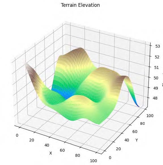
For the purpose of this case study, the overall mission is defined across a 100 x 100 spatial grid representing a synthetic landscape. The terrain elevation is generated to simulate realistic variations in surface elevation, such as hills, valleys and plateaus. From this landscape, the NAI is extracted using a process of percentile-based thresholding. This enables one portion of the map to be the area of interest.[61]
The NAI represents the primary zone for the reconnaissance operations. Terrain realism is important for modelling the flight paths, line-of-sight logic and environment-sensitive cost functions. The depots are placed randomly outside the NAI with the surrounding operational area. The planning process considers routes connecting the depot to the NAI, while the remaining area is excluded from the planning process.
Environmental and Operational Cost
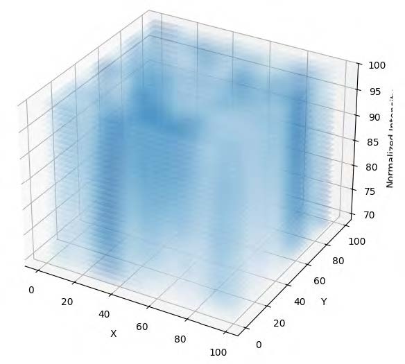
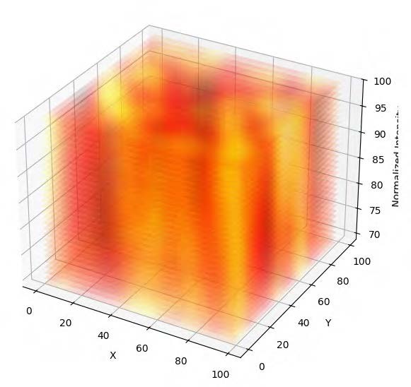
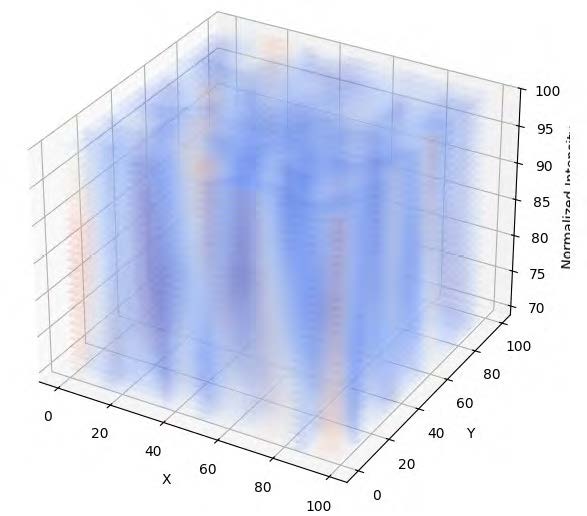
The simulation includes multiple environment fields across a 3D space to capture the difficulty of traversing the NAI. A weather map is simulated at each altitude level to emulate conditions such as cloud cover, turbulence, or visibility reductions. A risk map is also produced to represent hazards such as radar detection zones or naturally unsafe regions that could compromise aerial reconnaissance. The wind field is modelled using two components, horizontal and vertical flow, which are smoothed to create realistic wind magnitudes that vary with altitude.[62]
To further add to the realism, the simulated environment includes 3D bounded obstacles—i.e., zones that may represent no-fly zones, physical obstructions such as mountains, or airspace restricted for safety reasons. The obstacles are defined in the same NAI and span altitude ranges, effectively blocking any flight path. When calculating the routes, the pathfinding algorithm treats these zones as impassable, altering the cost of feasible routes.
A 3D cost map is produced by normalising each of the environmental fields to a common scale (including the 3D obstacles) and combining them with the priority maps. The final traversal cost at any point (altitude, y, x) is determined by a weighted sum of the weather, risk and wind factors.[63]
Priority Zones and Clustering
Reconnaissance tasks are concentrated within the NAI. The mission planner assigns reconnaissance priorities based on the expected intelligence value or the surveillance requirements of different regions. These variables are classified into three priority zones: high, medium and low. High-priority zones represent critical areas that demand frequent surveillance. They may include command centres, strategic infrastructure or conflict-sensitive zones. Medium-priority areas do not require constant monitoring. Low-priority zones are included for a baseline observation.
The priority zones are generated via a smoothed random field and are overlaid on the NAI. This smoothed field is then discretised using percentile thresholds to ensure a balanced—yet non-uniform—distribution of high-, medium- and low-priority targets across the NAI.
Every priority region is then segmented into connected clusters using region labelling techniques.[64] The clusters serve as the fundamental units for both mission planning and performance evaluation. By operating at a cluster level, the system allows for efficient vehicle assignment and scalable mission planning.
Altitude Levels and Sensor Resolution
The UAVs assigned for reconnaissance must operate at altitudes that can carefully balance sensor fidelity, ground coverage area and operational safety. The simulation presents three altitude levels, derived dynamically from the terrain. The system identifies the maximum terrain elevation, denoted by hmax to establish lowest safe flight altitude. The altitude range between hmax and the max ceiling is then divided into three altitude bands, representing operational layers for sensor deployment.[65]
Each of these altitude levels is mapped to a specific sensor resolution tier. To capture fine-grained information, the lowest altitude band is allocated the highest sensor resolution. The middle altitude level corresponds to medium sensor resolution, offering a compromise between detail and area coverage. The highest altitude level is assigned to low resolution sensors which can scan broader regions but with less precision.[66]
The altitude levels ensure that the flight paths respect both the terrain elevation and sensor-specific operating requirements.
Sensor Coverage Circles
Every reconnaissance task is anchored to a specific ground coordinate and paired with a sensor characterised by a field of view. To model the spatial reach of every sensor, the system projects its coverage as a circular footprint. The radius of this coverage circle is determined using a geometric relation derived from the sensor’s altitude and viewing angle:
Coverage radius = h⋅tan(θ)
Here, h represents the operating altitude associated with the task’s assigned resolution and theta is the sensor’s half angle of view, fixed at 15 degrees for this simulation.[67] The formulation captures how altitude-based sensors can observe larger ground areas, while lower-altitude sensors offer more localised but finer detail.
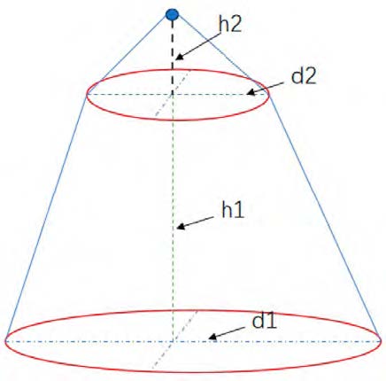
Image source: Multidisciplinary Digital Publishing Institute (MDPI) [68]
The coverage circles are projected onto the ground plane and visually overlaid on the terrain and reconnaissance priority maps. This indicates to the mission operator how well the priority zones are being scanned. During the performance evaluation, the system calculates the union of all active coverage areas with the priority region masks. This allows the system to quantify the percentage of each cluster that was observed during the mission hour.
Mission Planner
The mission planner functions as the scheduling engine responsible for coordinating reconnaissance operations across multiple vehicles over the course of a simulated mission. In every hourly cycle, it generates a plan which samples points from the high-, medium- and low-priority clusters that were identified from the NAI. Each point is randomly assigned a sensor resolution level, which dictates the altitude at which the vehicle would operate and the size of the ground area which it can cover. These points are then organised into vehicle-specific batches ensuring an even distribution across the fleet. The mission planner also generates an hourly percentage coverage for each of the priority zones.
The assigned batch of points is then converted into a set of 3D nodes and passed through a pipeline which combines 3D A* pathfinding[69] and either the Held-Karp algorithm or the QAOA. The result is a vehicle mission route generated by the optimisation pipeline that begins at the depot and visits all assigned points while avoiding hazardous zones. The predefined expectations laid out by the mission planner are then compared against the actual coverage achieved by the sensor footprints, forming the basis for feedback.
Vehicle Routing Using A*, Held-Karp and QAOA
The assigned tasks for each vehicle are converted into a list of 3D nodes where each node includes the operational altitude level along with the corresponding y,x ground coordinates. The route begins at a depot which is present outside of the NAI and includes all the points selected for the current mission hour.
To determine an efficient and environment-aware mission path, the system first employs a 3D A* pathfinding algorithm to compute the shortest cost paths between the pair of nodes. The paths are calculated using the precomputed 3D cost map, which accounts for terrain, weather, risk, wind conditions and altitude constraints. This step ensures that the traversal is not just the geometric distance. The calculated paths are cached to save computation time for the other nodes which might have similar starting points.
Once the pairwise paths are computed, two optimisation strategies are available. The first is the Held-Karp algorithm which is a dynamic programming approach to solve the TSP. A similar procedure for handling the routing is followed here. Nodes are first clustered to manageable sizes. The clusters with three or four nodes are then passed to the QAOA solver. The clusters with more than four nodes are passed to the Held-Karp solver.
On selecting the route candidate produced by either Held-Karp or QAOA—the A* algorithm is used again to complete the 3D route that connects the depot to the priority area points. The final route is then visualised showing the vehicle route, altitude levels covered and the sensor resolution. This hybrid quantum framework provides an environment aware routing solution while remaining modular and adaptable to different planning requirements.
Performance Evaluation: Expected Versus Actual Coverage
For every simulated hour of the mission, the system defines the expected coverage percentage for every cluster. These expectations simulate the goals set by the mission planner. Once the vehicle routes are generated and executed, the system calculates the actual coverage by analysing the union of all sensor coverage circles and intersecting them with the ground truth clusters.
The comparison between the expected and actual coverage provides a basis for evaluating the mission effectiveness. Clusters receiving less coverage may indicate underutilisation of resources or inefficient routing.[70]
Synthesis
Up to this stage, the paper has presented the mathematical modelling for both logistics resupply and reconnaissance operations. However, due to current hardware limitations, large-scale routing problems cannot yet be solved directly on a quantum computer. To address this limitation, the overall routing graph is decomposed into smaller, manageable clusters of nodes. Selected subproblems of suitable size are formulated as QUBO for execution using QAOA, while larger subproblems are handled using classical methods. This section presents the execution of the QUBO model on both a quantum simulator and a real quantum computer. The experiments were conducted using the IBM Fez computer.
Execution Environment and Qubit Projection
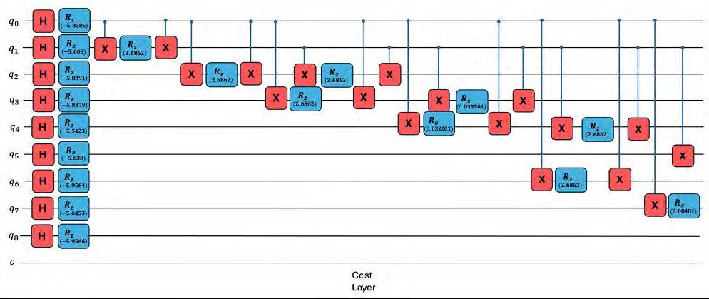
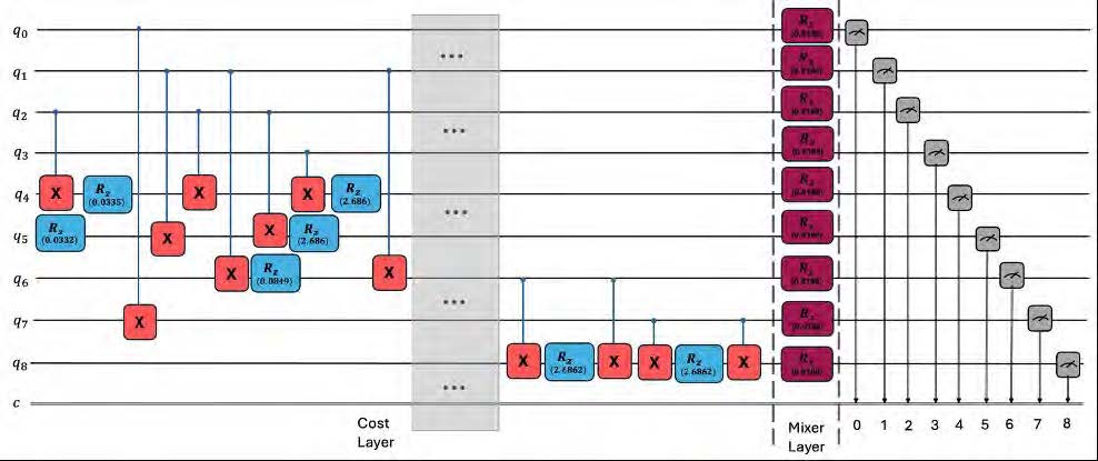
Figures 9 and 10 display a portion of the quantum circuit for a three-city node problem. The circuit uses 9 qubits. The cost matrix between the cities and depots is first converted into a QUBO representation and then into an Ising Hamiltonian. The city nodes are a part of a larger VRP. The overall problem has been deconstructed into smaller and tractable sub-problems.
The circuit begins with Hadamard gates placing each qubit into superposition. It is then followed by single qubit RZ gates which encode the linear terms of the Ising Hamiltonian. Two qubit interaction terms are implemented using the controlled X operations together with RZ rotations. The combination of the single qubit RZ gates and the two qubit gates make up the cost layer of the QAOA circuit. Rx gates are used as mixers in the QAOA circuit. COBYLA optimiser has been used for optimising the values of gamma and beta used in the QAOA circuit. In the present implementation, Aer simulations [71] were limited to four city problems as the  qubit encoding causes the memory requirement to grow exponentially with the number of qubits.
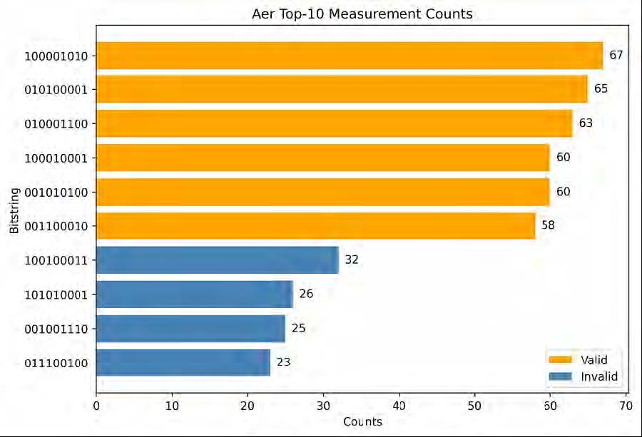
The orange bar shows the valid solution.
Figure 11 shows the top bit strings produced by the Aer simulator for the 3 city sub-problem. Every bit string shows a specific routing configuration over the cluster. The bar heights correspond to how frequently every result was observed. The bit strings in orange correspond to valid solutions, whereas the bitstrings in blue correspond to invalid and not feasible solutions. Of the ten most frequently measured bit strings, six were valid and four were invalid. The bit string ‘100001010' occurs 67 times in the output. Since this simulation was performed using the noiseless Aer simulator, the measured distribution is free from hardware induced gate and readout errors. This reflects the behaviour of the QAOA circuit in the absence of hardware noise.
IBM Fez Quantum Computer
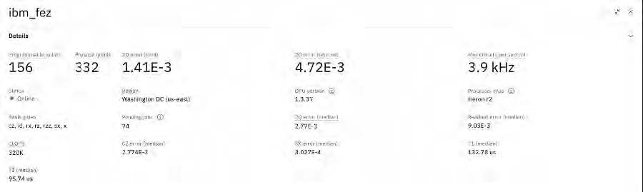
IBM’s Fez quantum system[72] was selected to implement our QAOA circuit due to its mid-scale architecture and optimised performance. IBM Fez is a 156-qubit quantum system built over IBM’s Heron r2 processor. To use this processor, the QAOA circuit must first be transpiled into the set of hardware-specific gates compatible with it.
The Fez quantum system operates within the following processing parameters. It can achieve an average T1 coherence time of 132.78 microseconds (‘T1 coherence time’ refers to the time it takes for a qubit to spontaneously relax from the excited state to ground state). The processor’s T2 coherence time averages around 95.74 microseconds (T2 coherence time measures how long a qubit can maintain phase coherence between the states). The system’s two-qubit gate operations (essential for entanglement and core to the QAOA) exhibit best-case error rates of 0.141 per cent, with a median error rate of 0.277 per cent. Measurement operations, or readout, have a median error rate of 0.903 per cent, reflecting the noise sensitivity of qubit state detection. The Fez system supports the following gate set: CZ (Controlled-Z), RX (X-axis rotation), RZ (Z-axis rotation), RZZ (Rotation-ZZ), ID (identity), SX (square-root of X) and X (bit-flip). The system achieves a throughput of 320,000 circuit operations per second (CLOPS), a metric that reflects both execution speed and efficiency.
Transpiled QAOA Circuit
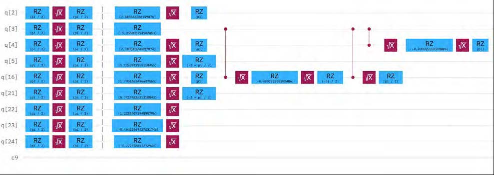
The simulation circuit has been transpiled with gates specific to IBM Fez.
Figure 13 shows a transpiled segment of the quantum circuit tailored specifically for execution on the IBM Fez quantum device. This image captures a partial snapshot of the final hardware-executable circuit because the full transpiled circuit contains hundreds of gates and gate operations which cannot be displayed in a single image due to size constraints.
Results from the Quantum Computer
Figure 14 below shows the top bit strings produced by executing the transpiled circuit on the real quantum hardware. Every bit string represents a specific routing configuration over the clustered travelling salesman sub-problem. The height of each bar shows how frequently each of the bit strings was observed. The bit strings marked in blue are invalid bit strings and do not translate into an actual route for the sub-problem. The bit strings which represent a valid route is marked in orange. Of the ten most frequently measured bit strings, five were valid and five were invalid.
The execution time for this run was 3 seconds. Due to the hardware noise, the measured bit string distribution differs from the noiseless simulation. The hardware experiment presented here used 9 logical qubits.
We assess that this simulation method is applicable to both logistics resupply and reconnaissance mission planning.
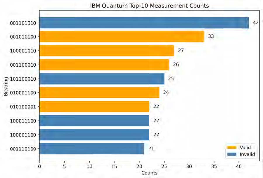
The orange bar shows the valid solution.
Logistics Resupply
Evaluation Criteria
The quality of the QAOA generated delivery routes was evaluated using an average optimality gap across the QAOA solved clusters. Lower bounds are commonly used in vehicle routing problems to provide a benchmark against which solution quality can be assessed [73]. Average optimality gap quantifies how close the QAOA derived route is to the optimal classical solution within each cluster. For each cluster solved using QAOA, optimality gap is calculated as the percentage difference between the route cost obtained from QAOA and the corresponding optimal route cost obtained using a classical benchmark solver. A smaller optimality gap indicates that the QAOA solution is closer to the optimal solution for that clustered subproblem, whereas a larger optimality gap indicates higher deviation of the QAOA solution from the optimal. For each scenario the average optimality gap was calculated across all clusters solved using QAOA.
In addition to the solution quality, every scenario’s computational time was recorded to evaluate the framework’s performance and scalability. The timing results also helped demonstrate the framework’s responsiveness to changes in input size and complexity.
Initial Results
|
ID |
Number of depots |
Number of nodes |
Number of vehicles |
Average optimality gap (%) |
Time elapsed (in seconds) |
|---|---|---|---|---|---|
| 0 | 1 | 10 | 2 | 4.18 | 11.3 |
| 1 | 1 | 20 | 4 | 0.59 | 18.72 |
| 2 | 1 | 30 | 5 | 4.44 | 30.53 |
| 3 | 2 | 10 | 2 | 0.00 | 12.84 |
| 4 | 2 | 20 | 4 | 0.00 | 19.39 |
| 5 | 2 | 30 | 5 | 3.53 | 27.04 |
| 6 | 3 | 10 | 2 | 1.89 | 12.16 |
| 7 | 3 | 20 | 4 | 0.00 | 42.06 |
| 8 | 3 | 30 | 5 | 0.00 | 26.87 |
| 9 | 4 | 30 | 5 | 5.55 | 24.09 |
| 10 | 7 | 90 | 16 | 3.85 | 68.29 |
| 11 | 8 | 85 | 15 | 1.93 | 67.28 |
| 12 | 8 | 90 | 16 | 2.75 | 75.35 |
| 13 | 8 | 95 | 16 | 0.81 | 74.43 |
| 14 | 9 | 80 | 14 | 2.49 | 80.38 |
| 15 | 9 | 95 | 16 | 0.00 | 94.34 |
| 16 | 12 | 150 | 25 | 1.51 | 104.75 |
| 17 | 12 | 175 | 31 | 1.29 | 122.15 |
| 18 | 12 | 190 | 33 | 1.45 | 132.80 |
| 19 | 15 | 230 | 39 | 0.84 | 152.59 |
| 20 | 15 | 250 | 44 | 0.59 | 248.62 |
| 21 | 15 | 275 | 49 | 0.66 | 176.93 |
| 22 | 16 | 280 | 48 | 0.57 | 392.54 |
| 23 | 16 | 295 | 52 | 0.70 | 191.39 |
| 24 | 16 | 305 | 53 | 0.71 | 269.44 |
Table 1 summarises the outcomes of 25 logistics resupply simulation scenarios with the average optimality gap and elapsed computation time (in seconds). For smaller-scale scenarios which involved one depot and up to 30 nodes, the system achieved low average optimality gaps ranging from 0.00 per cent to 5.55 per cent. Several configurations - including 2 depots with 10 and 20 nodes, and 3 depots with 10 or 20 nodes reached the optimal solution within specific clusters containing 3 cities. Computational times for these scenarios ranged from 11 to 42 seconds.
As the problem scale increased to between 80 and 95 nodes with up to 16 vehicles, the framework maintained strong solution quality, with average optimality gaps between 0.00% and 3.85% despite computational times increasing to approximately 67-94 seconds.
For the large-scale scenarios involving 150 to 305 nodes and p to 53 vehicles, the framework remains computationally tractable for the larger simulated scenarios. Average optimality gaps remained below 1.6% while the computation times varied between approximately 105 and 393 seconds.
Figures 15 to 18 below illustrate two simulation scenarios: one involving 16 depots and 305 cities, and another with a single depot and 30 cities.
Scenario 1: 16 Depots and 305 Cities
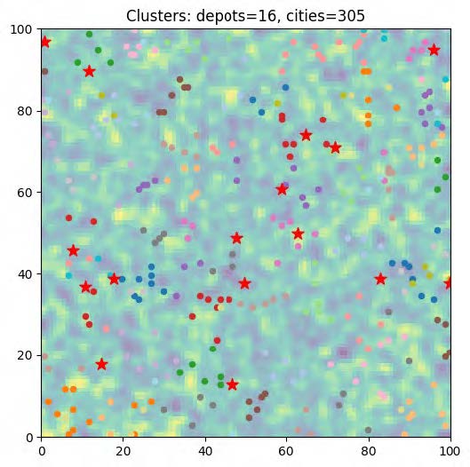
The cost map has been built by considering terrain, weather and risk factors. Circles are the cities and stars are the depots.
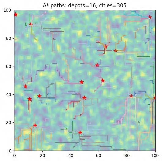
QAOA was used to determine the combinatorial ordering for the selected small routing subproblems.
Scenario 2: One Depot and 30 Cities
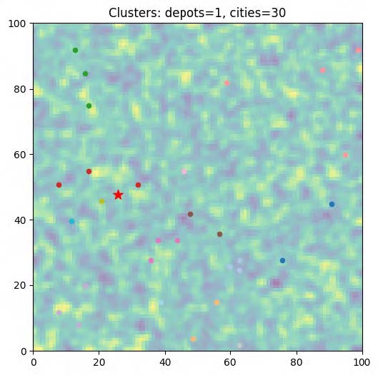
The cost map has been built by considering terrain, weather and risk factors. Circles are the cities and stars are the depots.
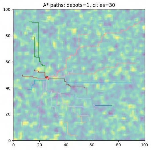
QAOA was used to determine the combinatorial ordering for the selected small routing subproblems.
Factors for Real-World Deployment
While the outcomes of the simulations are promising, the framework is not yet ready for deployment in a real-world operational environment. Several critical factors must first be addressed to ensure reliability, accuracy, security and integration of the framework with existing digital and tactical ecosystems.
Data quality. The first foundational requirement is access to genuine and high-quality data. Terrain models can be sourced from lidar inputs or satellite-derived datasets. These can accurately represent topological features such as hills, gullies, bridges, riverbeds and road infrastructure. Local weather stations can contribute to the live readings on wind, rainfall and temperature. Satellite imagery and field intelligence reports can provide overlays of tactical risk, including hostile activity zones. These inputs can replace the synthetic 100 x 100 grid. These data layers need to update frequently—ideally every few minutes—and they must pass automated sanity checks to catch anomalies such as duplicate coordinates and unrealistic slopes.
Systems integration. Once the data pipelines are operational, the framework must integrate seamlessly into the base’s digital architecture. Once vehicle sensors, fuel monitors and position transponders have transmitted the telemetry data to a control centre, the optimiser must be able to consume these data streams directly rather than requiring manual input. System protocols are also needed. For example, when a route is computed it should be published in an agreed protocol—such as XML or binary messages. A well-documented and clean API allows other tools to read or update routes programmatically. Further, the software must exhibit modular architecture, enabling individual components to be pathed or upgraded independently.
Validation processes. The optimiser must pass extensive stress testing and fault injection.[74] This would include simulated failures such as a collapsed bridge or corrupted GPS signals. The system must either refuse to generate invalid routes or flag the unresolvable conditions. Historical back-testing is equally important; re-running past scenarios and comparing the predicted outcomes helps uncover system modelling errors. These validation steps feed into the certification channels which are required for systems operating in the military networks.
Cybersecurity. This is another pillar of deployment readiness. The system must adhere to regular operating system patching, encrypted storage, multi-factor authentication and full audit trails. The outbound communication (whether via fibre link, cloud endpoint or vehicle radio) must be encrypted end to end and signed to prevent tampering. The optimiser must also be resistant to infrastructure denial, and a cached copy of the most recent cost data must be maintained and able to operate from a universal patching system for long enough to generate a fallback plan in the event of a power loss.[75]
Adaptability. The optimiser must be adaptable to the mission context. For routes in real time, the processing must occur within the operations centre. This reduces dependency on cloud or remote systems that can be unreachable at times. By contrast, overnight simulations can utilise high-capacity compute resources. If quantum accelerators are available, then characteristics such as noise, latency and calibration drift must be evaluated. The system must also be supported by a classical fallback that meets a fixed performance budget.
Human–machine teaming. Humans-in-the-loop systems are not an afterthought. Planners should be able to interact with the routes by dragging cities (repositioning the cities/points on the map) to reprioritise them, deleting a city node entirely or locking essential deliveries such as ammunition ahead of water. These actions must be informed by real-time updates concerning cost and delivery feasibility. When the optimiser suggests a route adjustment, the justification needs to be clear. Rapid onboarding tools must be supported by timely training to ensure that users are proficient in the framework.
Feedback loops. After each mission, actual fuel usage and travel time should be written back to the system allowing data scientists to improve the cost models. An automated testing pipeline should validate all software updates against a dataset of known edge cases before release. A well-documented code base (modular in nature) ensures that any policy changes or environmental models can be introduced with minimal code disruption.
Red teaming. The system must be robust against adversarial threats. Red-team scenarios such as spoofed terrain map and forged sensor inputs should be used for hardening the system against compromised data. In multi-unit settings, the framework must also support federated planning, enabling secure coordination across organisations using logistic data protocols and encryption practices.
In sum, real-world deployment of the logistics resupply framework demands a rigorous intersection of data realism, system integration, security, resilience and usability. These layers ensure that the system not only computes the routes efficiently but also does it in a trustworthy, transparent way.
Reconnaissance
Methodology
The reconnaissance methodology follows a similar approach to the logistics optimisation framework. Priority points within the NAI are treated as the equivalent nodes of the optimisation problem. Flight paths are generated from the depot locations while considering operational constraints such as fuel range and vehicle capability. A weighted cost matrix is generated using terrain, weather, wind and risk factors. These weighted values influence the routing decisions produced by the optimisation framework. The reconnaissance area is also divided into high-, medium- and low-priority zones to support priority-based mission planning.
Due to current quantum hardware limitations, large-scale optimisation problems cannot be solved directly on a quantum computer. To address this issue, the reconnaissance points are divided into smaller and manageable clusters. As the number of points increases, additional clustering is performed to maintain computational feasibility. High-priority clusters are processed first to maximise mission coverage over critical regions. Clusters with three or four nodes are selected for QAOA and are converted into a QUBO formulation and evaluated using a quantum simulator and for selected cases, the IBM quantum computer. Larger clusters are handled by the classical Held-Karp solver. The resulting routes and coverage outputs are compared to evaluate the effectiveness of the reconnaissance mission.
Evaluation Criteria
Evaluating the effectiveness of a reconnaissance mission was achieved using two criteria: percentage cover and percentage redundancy. In combination, these indicators showed how thoroughly the area was captured and how efficiently the resources were utilised.
- Percentage cover: measures the extent to which the reconnaissance system successfully observed the priority zones within the NAI. This metric was computed as the proportion of each priority cluster which fell within the sensor coverage footprint. Since each reconnaissance point was associated with a certain sensor radius (determined by altitude and resolution), the system calculated the union of all simulated ground coverage areas and intersected it with the cluster masks. A high coverage percentage signified that the mission met or exceeded the expectation goals.
- Percentage redundancy: refers to the proportion of the total ground area covered by multiple sensors—via either overlapping footprints or multiple revisits. While some degree of overlap is necessary, excessive overlap suggested inefficient use of resources. Redundancy was particularly important to track when the coverage limits were exceeded (i.e., when the system continued to dispatch sensors beyond what was required), because it provided opportunities to better optimise vehicle allocation, reroute flights or shift to under-focused regions.
Together coverage and redundancy offered a balanced view of mission performance. High coverage with low redundancy implied a lean and effective mission; high coverage with high redundancy pointed towards potential inefficiencies in route planning. The metrics were evaluated per hour, per vehicle and per cluster and were presented as a post-mission report.
Initial Results
|
Vehicle |
Expected coverage (high priority) |
Actual coverage (high priority) |
Expected coverage (medium priority) |
Actual coverage (medium priority)
|
|---|---|---|---|---|
| 0 | 43.89 | 75.00 | 42.08 | 75.19 |
| 1 | 43.89 | 100.00 | 42.08 | 40.00 |
| 2 | 43.89 | 53.53 | 42.08 | 87.57 |
| 3 | 43.89 | 100.00 | 42.08 | 100.00 |
Table 2 summarises the performance of four vehicles during the first hour of a simulated reconnaissance mission. The table contains a fraction of the vehicles and priority zones which were considered. The expected coverage value for the high-priority zones was consistent across all vehicles at 43.89 per cent. Actual performance varied from vehicle to vehicle.
- Vehicle 0 exceeded expectations at 75 per cent.
- Vehicle 1 and 3 achieved full coverage.
- Vehicle 2 fell short at 53.53 per cent.
For the medium-priority regions, the expected coverage was consistent at 42.08 per cent. The actual coverage ranged from 40 per cent to 100 per cent.
- Vehicle 0 exceeded expectations at 75.19 per cent.
- Vehicle 1 fell short at 40 per cent coverage.
- Vehicle 2 exceeded expectations at 87.57 per cent.
- Vehicle 3 achieved complete coverage.
Figures 19 to 26 below show the reconnaissance mission planning outcomes for the two scenarios considered in this study. The figures include the NAI, depot locations, priority zones, overall discretisation of the NAI into a grid, priority points allocated within each zone, and sensor coverage points associated with the allocated vehicles.
Scenario 1

High priorities have darker shades. Depots have been randomly chosen on the map.
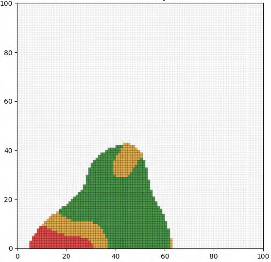
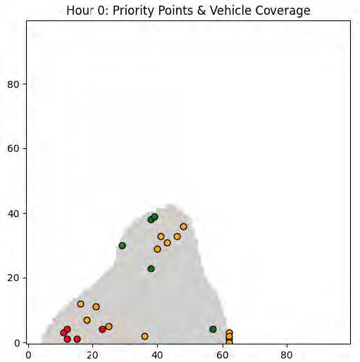
The allocation is random and is updated every hour based on the mission planner. Each point has a resolution and altitude.
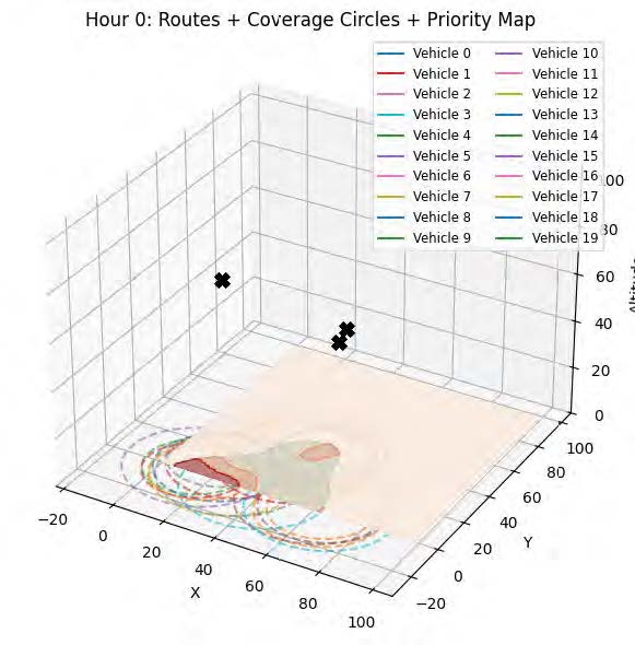
The coverage circles change according to the resolution and the altitude.
Scenario 2
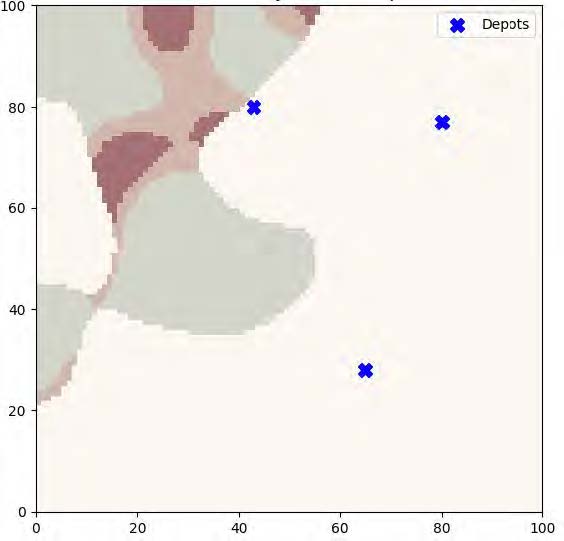
High priorities have darker shades. Depots have been randomly chosen on the map.
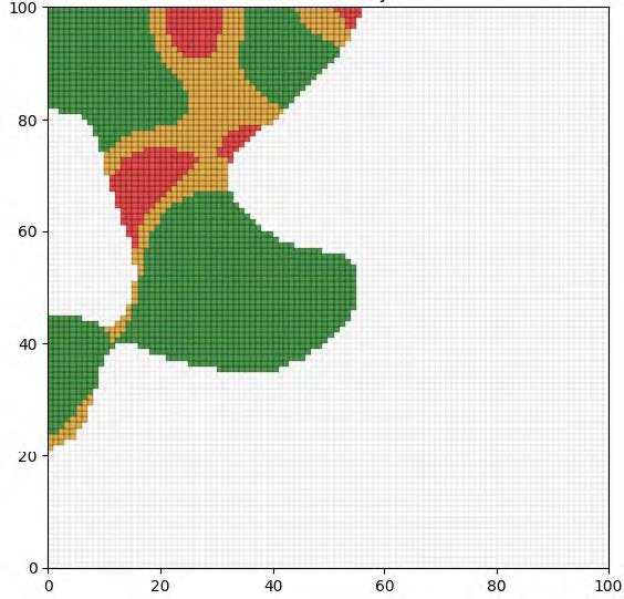
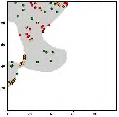
The allocation is random and is updated every hour based on the mission planner. Each point has a resolution and altitude.
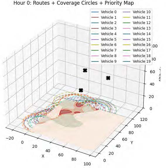
The coverage circles change according to the resolution and the altitude.
Factors for Real-World Deployment
Deploying a 3D reconnaissance planning framework into a military operational setting presents unique challenges by comparison with the 2D logistics resupply example. From altitude-sensing models to changing airspace and turbulence, a reconnaissance system will need to be rigorously tested and integrated if it is to function reliably. The key challenges can be summarised as follows.
Airspace modelling. The framework requires that the operational space is represented as a 3D voxel grid where every cell encodes traversal cost as a function of terrain, weather and risk. Unlike ground vehicles, aerial vehicles operate across flight levels, requiring the system to reason about vertical transitions and minimum safe altitudes. This voxel-based structure replaces a simple grid-based structure and presents more computational demands.[76]
Instead of being a delivery point (as in logistics resupply), here every task is a surveillance objective with a certain coverage requirement. The system must therefore be able to calculate the ground coverage footprint of every sensor based on the field of view, altitude and orientation. Reconnaissance missions will often demand that targets are captured with a specific angle, resolution and revisit frequency, all of which are factors influenced by sensor altitude and vehicle trajectory.
Environmental modelling. The framework must process both terrain and weather fields that vary with altitude, such as wind shear, thermal layers, air pressure and icing conditions. Real-time feeds must be continuously integrated with the 3D cost model.
Regulatory requirements. The system must respect regulatory issues around airspace constraints and aerial governance. UAVs cannot fly arbitrarily. They must comply with controlled air corridors, altitude rules and restricted or no-fly zones. These constraints may not be static; they may change as the military operation proceeds through different regulatory zones. The framework must be able to ingest this information and integrate it into the planning logic.
Vehicle modelling. Reconnaissance platforms, whether fixed-wing or multi-rotor UAVs, are subject to a wider range of flight and fuel constraints than land-based vehicles. Each platform must be modelled for climb rate, hover endurance, battery capacity and sensor payload weight. Instead of only focusing on the fuel tank limit, the system must evaluate mission range based on these factors and associated environmental resistance. Planning to return to base becomes more complex, often requiring redundant paths in case of mid-mission faults.
Validation processes. Before the system can be integrated with reconnaissance assets, the sensor must undergo flight validation and sensor coverage testing. This would include simulating visibility obstructions due to terrain, confirming altitude sensor compatibility and validating the system’s ability to generate alternative routes when weather, risk or altitude violations are detected. Fault injection testing is also essential to simulate UAV failure, mid-flight GPS dropout or cloud obstruction. In such cases, the system must respond with replanning.
Systems integration. The system must be integrated with air operations infrastructure. UAV telemetry must be ingested in real time. Task updates must be dispatched in protocols compatible with mission control software, ground control stations or on-board flight computers. This is likely to require MAVLink or other mission system compatible message formats.[77]
Cyber security. Aerial vehicles must be resilient to cyber threats; a compromised drone can pose security threats. Mission data, telemetry and route updates must therefore be logged, encrypted and signed with full traceability.[78]
Useability. Field operators must be able to visually reposition and adjust the sensor coverage areas on a visual interface, assign coverage priorities and reallocate flights with minimal training. If a detour is proposed, it should include justification such as ‘target now within sensor resolution’, allowing the planner to act quickly with confidence.
Feedback loops. After every mission, the actual flight path, sensor logs and coverage outcomes must be fed back into the optimiser. This will enable the model to be refined to improve energy estimation, sensor performance prediction and mission duration forecast. Historical replay of previous missions with dynamic environmental layers also helps to determine whether model updates have improved or degraded performance. An automated testing pipeline should validate any software update against edge cases before deployment.
In summary, deploying a 3D aerial reconnaissance system requires a deep and integrated approach across altitude-aware modelling and real-time sensing, and it must be supported by operational transparency.
Future Directions and Conclusion
Future Directions
The field of quantum optimisation for RAS in logistics resupply and reconnaissance is still in its early stages. A primary challenge to address is a lack of familiarity among military stakeholders with quantum techniques, including quantum optimisation algorithms. Developing methods to clearly explain the nature and benefits of quantum outputs to Army decision-makers and planners will be essential if quantum algorithms are to be adopted for use in military operations.[79]
Beyond addressing the issue of unfamiliarity with quantum technology, there is still much substantive research to be done if quantum techniques are to be effectively used to optimise the achievement of military logistics resupply and reconnaissance tasks.
Pure-quantum processes. Work undertaken to date relies on hybrid quantum-classical systems where quantum processors handle certain parts of the optimisation while classical processors perform the bulk of the tasks. Future research may investigate whether a greater proportion of the optimisation workflow can be executed on a quantum hardware as the technology matures. A full quantum approach would present significant optimisation opportunities, particularly for large-scale problems which are difficult for classical systems to solve. However, there are several key challenges to the development of fully quantum solutions. These include the need to increase the qubit stability of quantum hardware, to scale up qubit counts and to reduce noise. As the hardware matures, research should focus on identifying what optimisation problems can be handled by quantum processors alone and how these can be scaled for large-scale military operations.[80]
Error mitigation in quantum algorithms. This remains one of the most critical challenges for practical deployment in real-world scenarios. Current quantum computers are susceptible to errors caused by factors such as noise, decoherence, and operational inaccuracies. These factors can significantly impact the accuracy and reliability of quantum solutions. As quantum processors become more advanced, there will be an associated need for error-correction techniques that ensure the reliable performance of optimisation algorithms. Future research should therefore investigate both error mitigation techniques for near term hardware and, as fault tolerant systems mature, quantum error correction approaches that can improve the reliability of larger optimisation circuits.[81]
Distributed quantum computation. Many real-world logistics resupply and reconnaissance problems involve large-scale systems which require more computation power than could be provided by a single quantum processor. By distributing quantum computation across multiple quantum devices and classical systems, the opportunity exists to leverage the strengths of both technologies to solve larger optimisation problems. Future work should therefore focus on developing distributed quantum computing frameworks that enable parallelism. This could improve scalability and flexibility, enabling systems to solve problems far beyond the capacity of current quantum hardware.[82]
Warm-start methods for QAOA. Algorithms like QAOA rely on the initialisation of the quantum system, which can affect the efficiency of the optimisation process. The development of better techniques for initialising QAOA has the potential to improve its performance, specifically in large-scale problems. Research should therefore focus on automatic warm-start methods which can adjust the parameters based on the specific characteristics of the problem. Better warm-start methods may improve convergence behaviour and increase the likelihood of obtaining high-quality solutions.[83]
Additional methodologies. Other quantum methodologies such as quantum annealing and variational quantum eigensolver (VQE) could also be included in the framework. Each of these methods has its respective strengths; by combining them, it would be possible to achieve better performance on certain problems. For instance, quantum annealing could be more suitable for certain combinatorial problems such as routing, scheduling and task allocation. In contrast, VQE is more applicable to optimisation problems which involve continuous parameter adjustment such as sensor parameter tuning or adaptive resource management. Future work should explore how the combination of these methods could be used in the existing framework in order to enhance system flexibility and adaptability.
Multi-objective optimisation techniques. Military logistics often involves balancing multiple objectives, such as minimising time, cost and risk while maximising efficiency. In practice, military planners must make trade-offs between these considerations. By developing an optimisation approach that can satisfy several objectives simultaneously, options could be made available to better balance these competing considerations.[84]
Quantum and edge computing. The integration of quantum computing with edge computing is another promising area for future work. The term ‘edge computing’ refers to processing data closer to where it gets generated rather than sending all of the data to a distant central server. An example of edge computing could be processing the data on board a UAV or a nearby server system. By integrating quantum optimisation algorithms with edge computing, some preprocessing and decision support could be performed closer to the data source, potentially reducing overall system latency and improving responsiveness of the system. Research should focus on how optimisation algorithms can be adapted for deployment in edge computing environments. This could enhance the robustness of RAS systems in dynamic environments.
Sustainability. Long-term operational sustainability will be essential for widespread adoption of quantum techniques within the Army. Therefore, longer term research should focus on developing energy-efficient quantum computing solutions that can be deployed in mobile environments.
In summary, the future of quantum optimisation for RAS in logistics and reconnaissance holds great promise. While there are several challenges that must be addressed, the development of hardware and algorithms will pave the way for efficient and adaptable systems.
Conclusion
This paper has explored the potential of hybrid quantum optimisation techniques for logistics resupply and reconnaissance in the context of RAS. The research indicates that hybrid quantum classical methods can provide a useful framework for investigating selected optimisation problems.
The core contribution of this work is the development of a hybrid quantum classical model to enhance the achievement of both logistics resupply and reconnaissance missions. To work within the current scalability limits of current quantum optimisation approaches, the paper proposes a framework that decomposes large scale mission planning problems into smaller, computationally manageable subproblems. This framework has been achieved using hierarchical clustering and A* pathfinding algorithms alongside the QAOA for combinatorial optimisation.
The initial findings show that this approach has the potential to improve the efficiency of logistics and reconnaissance operations. Importantly, the modular architecture presented here has the potential to support scalable and robust outcomes, even in scenarios where quantum processors have a scheduled downtime. This flexibility is a crucial step in the integration of these algorithms into existing military infrastructures, without requiring significant changes to workflows.
In terms of security and resilience, the paper highlights the importance of protecting mission-critical data. Future work should focus on developing robust fallback mechanisms that maintain performance under suboptimal conditions. There could also be classical backups in cases where quantum processors face scheduled maintenance, ensuring mission continuity.
Finally, the paper has outlined several promising avenues for further research. These include the development of explainable models for quantum optimisation, the pursuit of full quantum solutions, and the refinement of error mitigation techniques. Generating the ability to respond rapidly to unexpected scenarios (such as mission reprioritisation) is expected to be a game changer in the military sector. Expansion of the hybrid quantum-classical framework into a distributed setting, and incorporating multi-objective strategies, will be crucial for such techniques to be fully operationalised. In this way, the concept of quantum assisted optimisation can transition from theoretical models to practical deployable solutions that have the potential to reshape the way logistics and reconnaissance missions are planned and executed.
To meet the computational demands of modern operations, many military organisations are now exploring the potential of quantum computing.[85] While it is still in the early stages, the combination of classical and quantum methods has the potential to revolutionise aspects of mission planning. As quantum computing and RAS platforms grow more capable, the opportunity to integrate them into a single operational fabric becomes more realistic. This paper offers a foundation for doing so—one that is focused on optimisation validated via simulation, and mindful of the tactical realities. With careful design, quantum-enhanced RAS can become a battlefield advantage.
Endnotes
[1] Australian Army, Robotic & Autonomous Systems Strategy v2.0 (Canberra: Commonwealth of Australia, 2022).
[2] Josh Schneider and Ian Smalley, ‘What Is Quantum Computing?’, IBM (website), at: https://www.ibm.com/think/topics/quantum-computing.
[3] Department of Defence, ‘Logistics Cell Critical to the Mission’, Department of Defence (website), 15 July 2024, at: https://www.defence.gov.au/news-events/news/2024-07-15/logistics-cell-critical-mission.
[4] Artur Pessoa, Ruslan Sadykov, Eduardo Uchoa and Francois Vanderbeck, ‘A Generic Exact Solver for Vehicle Routing and Related Problems’, Mathematical Programming 183, no. 1–2 (2020): 483–523.
[5] Venkat Padmasola, Zhaotong Li, Rupak Chatterjee and Wesley Dyk ‘Solving the Traveling Salesman Problem via Different Quantum Computing Architectures’, arXiv (2025).
[6] Edward Farhi, Jeffrey Goldstone and Sam Gutmann, ‘A Quantum Approximate Optimization Algorithm’, arXiv (2014).
[7] ‘Q-CTRL to Partner with Defence on Quantum Navigation Technologies’, press release, Q-CTRL (website), 11 July 2023, at: https://q-ctrl.com/blog/q-ctrl-to-partner-with-defence-on-quantum-navigation-technologies.
[8] ‘Summary of NATO’s Quantum Technologies Strategy’, NATO (website), 16 January 2024, at: https://www.nato.int/cps/en/natohq/official_texts_221777.htm.
[9] Department of Defence, SDIP 5—Development and Integration of Autonomous Systems (Canberra: Commonwealth of Australia, 2024).
[10] Australian Army, Robotic & Autonomous Systems Strategy.
[11] Schneider and Smalley, ‘What Is Quantum Computing?’.
[12] Gilles Brassard, ‘Brief History of Quantum Cryptography: A Personal Perspective’, arXiv (2005).
[13] ‘The Big Quantum Chill: NIST Scientists Modify Common Lab Refrigerator to Cool Faster with Less Energy’, National Institute of Standards and Technology (website), 23 April 2024, at: https://www.nist.gov/news-events/news/2024/04/big-quantum-chill-nist-scientists-modify-common-lab-refrigerator-cool.
[14] Jwo-Sy Chen et al., ‘Benchmarking a Trapped-Ion Quantum Computer with 30 Qubits’, Quantum 8 (2024): 1516.
[15] Neil Na, Chou-Yun Hsu, Erik Chen and Richard Soref, ‘Room-Temperature Photonic Quantum Computing in Integrated Silicon Photonics with Germanium–Silicon Single-Photon Avalanche Diodes’, APL Quantum 1, no. 3 (2024): 036123.
[16] Cierra Choucair, ‘Scalable Silicon Spin Qubits Achieve Over 99% Fidelity for Quantum Computing with CMOS Technology’, Quantum Insider, 23 October 2024.
[17] ‘What Is Quantum Error Correction?’, Q-CTRL (website), at: https://q-ctrl.com/topics/what-is-quantum-error-correction.
[18] Ross Shillito, Florian Hopfmueller, Bohdan Kulchytskyy and Pooya Ronagh, ‘Compact Pulse Schedules for High-Fidelity Single-Flux Quantum Qubit Control’, arXiv (2023).
[19] Ali Javadi-Abhari et al., ‘Quantum Computing with Qiskit’, arXiv (2024).
[20] ‘CIRQ’, Google Quantum AI (website), at: https://quantumai.google/cirq.
[21] Sandeep Suresh Cranganore, Vincenzo De Maio, Ivona Brandic and Ewa Deelman, ‘Paving the Way to Hybrid Quantum–Classical Scientific Workflows’, Future Generation Computer Systems 158 (2024): 346–366.
[22] Australian Army, Army Quantum Technology Roadmap (Canberra: Commonwealth of Australia, 2021).
[23] ‘Quantum Technology’, Australian Army Research Centre (website), at: https://researchcentre.army.gov.au/rico/quantum-technology.
[24] ‘Improving Army Logistics with Quantum Computing’, Q-CTRL (website), at: https://q-ctrl.com/case-study/improving-army-logistics-with-quantum-computing.
[25] ‘New Quantum Project to Enhance Secure Timing’, media release, Defence (website), 14 April 2025, at: https://www.defence.gov.au/news-events/releases/2025-04-14/new-quantum-project-enhance-secure-timing.
[26] Luke A Nicastro, AUKUS Pillar 2 (Advanced Capabilities): Background and Issues for Congress (Congressional Research Service, 2024).
[27] ‘Cryoclock: An Edge Significantly Boosting JORN’s Capabilities’, BAE Systems (website), at: https://www.baesystems.com/en-aus/insight/cryoclock-an-edge-significantly-boosting-jorns-capabilities.
[28] ‘QuantaQuest Project Explores Application of Quantum Technologies in Defence’, European Defence Agency (website), 19 January 2024, at: https://eda.europa.eu/news-and-events/news/2024/01/19/quantaquest-project-explores-application-of-quantum-technologies-in-defence.
[29] Sheng-Kai Liao, ‘Micius Satellite Enables Intercontinental Quantum Communications’, SciTechDaily, at: https://scitechdaily.com/micius-satellite-enables-intercontinental-quantum-communications.
[30] ‘China Reveals Prototype Configuration of Jam Resistant and Counter-Stealth “Quantum Radar”’, Defense Systems Information Analysis Center (website), at: https://dsiac.dtic.mil/articles/china-reveals-prototype-configuration-of-jam-resistant-and-counter-stealth-quantum-radar.
[31] Vehicle Routing Optimization (LINDO Systems), at: https://www.lindo.com/library/VehicleRoutingProblems.pdf.
[32] Shawn McKay et al., Automating Army Convoys: Technical and Tactical Risks and Opportunities (Santa Monica CA: RAND, 2020).
[33] Jian Zhang, Kelin Luo, Alexandre M Florio and Tom Van Woensel, ‘Solving Large-Scale Dynamic Vehicle Routing Problems with Stochastic Requests’, arXiv (2022).
[34] Jeremy Fetter, ‘Contested Logistics—Army’s Role in the Joint Force’, The Cove, 17 March 2023, at: https://cove.army.gov.au/article/contested-logistics-armys-role-joint-force.
[35] Kai Huang and Michael Xu, ‘Optimization Models for the Vehicle Routing Problem under Disruptions’, Mathematics 11, no. 16 (2023): 3521.
[36] Rebekah S McKenna, Matthew J Robbins, Brian J Lunday and Ian McCormack, ‘Approximate Dynamic Programming for the Military Inventory Routing Problem’, Annals of Operations Research 288, no. 1 (2020): 391–416.
[37] Jian Zhang and Hailong Huang, ‘Occlusion-Aware UAV Path Planning for Reconnaissance and Surveillance’, Drones 5, no. 3 (2021): 98.
[38] Stefano Primatesta, Giorgio Guglieri and Alessandro Rizzo, ‘A Risk-Aware Path Planning Strategy for UAVs in Urban Environments’, Journal of Intelligent & Robotic Systems 95, no. 2 (2019): 629–643.
[39] https://www.benning.army.mil/Armor/eARMOR/content/issues/2015/JUL_SEP/3ScreenLine15.pdf
[40] Talha Azfar, Osama Muhammad Raisuddin, Ruimin Ke and Jose Holguin-Veras, ‘Quantum-Assisted Vehicle Routing: Realizing QAOA-Based Approach on Gate-Based Quantum Computer’, arXiv (2026).
[41] Peter E Hart, Nils J Nilsson and Bertram Raphael, ‘A Formal Basis for the Heuristic Determination of Minimum Cost Paths’, IEEE Transactions of Systems Science and Cybernetics SSC-4, no. 2 (1968).
[42] Michael X Goemans and Dimitris J Bertsimas, ‘Probabilistic Analysis of the Held and Karp Lower Bound for the Euclidean Traveling Salesman Problem’, Mathematics of Operations Research 16, no. 1 (1991).
[43] Shashank Sanjay Bhat, Udaya Parampalli, Joseph West and Tansu Alpcan, ‘Quantum RAS Planning’, Australian Army Journal 22, no. 2 (2026).
[44] Kyungtaek Jun, ‘QUBO Formulations for Numerical Quantum Computing’, arXiv (2021).
[45] Yuxin Pan, Ruohong Liu, Yize Chen, Zhiguang Cao and Fangzhen Lin, ‘Hierarchical Learning-Based Graph Partition for Large-Scale Vehicle Routing Problems’, arXiv (2025).
[46] Ratchadakorn Poohoi, Kanate Puntusavase and Shunichi Ohmori, ‘Stas Crossover with K-mean Clustering for Vehicle Routing Problem with Time Window’, Decision Science Letters 13 (2024).
[47] ‘Vehicles Routed with Efficient Use of Qubits’, Centre for Quantum Technologies (website), at: https://www.cqt.sg/highlight/2024-06-vehicle-routing-efficient-qubits.
[48] Jinming Zhang, Xun Wang, Lianrui Xu and Xin Zhang, ‘An Occupancy Information Grid Model for Path Planning of Intelligent Robots’, ISPRS International Journal of Geo-Information 11, no. 4 (2022): 231.
[49] Julia Bell and Tiffany Glenn, ‘Enhanced Military Operations Planning and Analysis with ArcGis’, Esri (website), 7 October 2024, at: https://www.esri.com/arcgis-blog/products/allsource/defense/enhanced-military-operations-planning-and-analysis-with-arcgis.
[50] Dongkyu Lee, I Made Aswin Nahrendra, Minho Oh, Byeongho Yu and Hyun Myung, ‘TRG-Planner: Traversal Risk Graph-Based Path Planning in Unstructured Environments for Safe and Efficient Navigation’, arXiv (2025).
[51] David R Levy, Multiple Vehicle Routing Problem with Fuel Constraints, Master’s thesis, Texas A&M University, 2013, at: https://oaktrust.library.tamu.edu/server/api/core/bitstreams/8a8ee276-ff42-4e9b-8ed1-9df2f24b2743/content.
[52] https://proceedings.esri.com/library/userconf/proc05/papers/pap2493.pdf
[53] https://www.nato.int/docu/logi-en/1997/lo-405.htm
[54] Yangqi Ou, Yuexin Fan, Xinglan Zhang, Yanhua Lin and Weijing Yan, ‘Improved A* Path Planning Method Based on the Grid Map’, Sensors 22, no. 16 (2022): 6198.
[55] Steve Rabin and Nathan R Sturtevant, ‘Pathfinding Architecture Optimizations’, in Game AI Pro 360: Guide to Movement and Pathfinding, 1st edition (CRC Press, 2019).
[56] ‘Traveling Salesperson Problem with QUBO’, Mathworks (website), at: https://www.mathworks.com/help/matlab/math/quantum-tsp.html.
[57] Andrew Lucas, ‘Ising Formulations of Many NP Problems’, arXiv (2013).
[58] ‘Held-Karp Algorithm’, Wikipedia, at: https://en.wikipedia.org/wiki/Held%E2%80%93Karp_algorithm.
[59] ‘Capacitated Vehicle Routing Problem Formulation’, AIMMS (website), at: https://how-to.aimms.com/Articles/332/332-Formulation-CVRP.html.
[60] Jianghua Zhang, Yingxue Zhao, Weili Xue and Jin Li, ‘Vehicle Routing Problem with Fuel Consumption and Carbon Emission’, International Journal of Production Economics 170 (2015): 234–242.
[61] ‘Named Area of Interest’, Military Dictionary (website), at: https://www.militarydictionary.org/term/named-area-of-interest.
[62] YY Chan, ‘Wind Dynamic and Energy-Efficiency Path Planning for Unmanned Aerial Vehicles in the Lower-Level Airspace and Urban Air Mobility Context’, Sustainable Energy Technologies and Assessments 57 (2023): 103202.
[63] Xinting Hu, Bizhao Panhg, Fuqing Dai and Kin Huat Low, ‘Risk Assessment Model for UAV Cost-Effective Path Planning in Urban Environments’, IEEE Access 8 (2020): 150162–150173.
[64] ‘Connected-Component Labeling’, Wikipedia, at: https://en.wikipedia.org/wiki/Connected-component_labeling.
[65] Luciano Blasi, Egidio D’Amato, Massimiliano Mattei and Immacolata Notaro, ‘UAV Path Planning in 3-D Constrained Environments Based on Layered Essential Visibility Graphs’, IEEE Transactions on Aerospace and Electronic Systems 59, no. 3 (2023): 2359–2375.
[66] Shaozu Ding, Yihong Tang, Marco De Vincenzi and Dajiang Suo, ‘High and Low Resolution Tradeoffs in Roadside Multimodal Sensing’, arXiv (2024).
[67] Yongkang Li, Tianyu Huo, Chenxi Yang, Tong Wang, Juan Wang and Beiyu Li, ‘An Efficient Ground Moving Target Imaging Method for Airborne Circular Stripmap SAR’, Remote Sensing 14, no. 1 (2022): 210.
[68] https://www.mdpi.com/applsci/applsci-15-01988/article_deploy/html/images/applsci-15-01988-g001.png

[69] Zhou Guoxin, LiuTing and XuYang, ‘3D Route Planning of Unmanned Aerial Vehicles in Dense and Complex Urban Environment’, in Liang Yan, Haibin Duan and Yimin Deng (eds), Advances in Guidance, Navigation and Control, vol. 1354, Lecture Notes in Electrical Engineering (Singapore: Springer Nature Singapore, 2025), pp. 202–213.
[70] Savvas D Apostolidis, Pavlos Ch Kapoutsis, Athanasios Ch Kapoutsis and Elias B Kosmatopoulos, ‘Cooperative Multi-UAV Coverage Mission Planning Platform for Remote Sensing Applications’, Autonomous Robots 46, no. 2 (2022): 373–400.
[71] ‘AERSimulator’, Qiskit Aer 0.17.1 (website), at: https://qiskit.github.io/qiskit-aer/stubs/qiskit_aer.AerSimulator.html.
[72] ‘Compute Resources’, IBM Quantum Platform (website), at:
https://quantum.cloud.ibm.com/computers?resourceType=current-instance&system=ibm_fez
[73] ‘Lower Bounds for Vehicle Routing Problems’, Hexaly (website), 1 March 2021, at:
https://www.hexaly.com/announcement/lower-bounds-vehicle-routing-problems.
[74] https://hogonext.com/how-to-conduct-fault-injection-testing-to-simulate-failures/
[75] Scott Rose, Oliver Borchert, Stu Mitchell and Sean Connelly, Zero Trust Architecture, NIST Special Publication 800-207 (US Department of Commerce, 2020).
[76] Scott Fredriksson, Akshit Saradagi and George Nikolakopoulos, ‘Voxel Map to Occupancy Map Conversion Using Free Space Projection for Efficient Map Representation for Aerial and Ground Robots’, arXiv (2024).
[77] ‘Mission (Plan) Protocol’, MavLink (website), at: https://mavlink.io/en/services/mission.html.
[78] ‘UAS Cybersecurity’, Cybersecurity & Infrastructure Security Agency (website), at: https://www.cisa.gov/topics/physical-security/be-air-aware/uas-cybersecurity.
[79] Raoul Heese, Thore Gerlach, Sascha Mücke, Sabine Müller, Matthias Jakobs and Nico Piatko, ‘Explaining Quantum Circuits with Shapley Values: Towards Explainable Quantum Machine Learning’, arXiv (2023).
[80] Amira Abbas et al., ‘Challenges and Opportunities in Quantum Optimization’, Nature Reviews Physics 6 (2024): 718–735.
[81] Zhenyu Cai et al., ‘Quantum Error Mitigation’, Reviews of Modern Physics 95, no. 4 (2023): 045005.
[82] Marcello Caleffi et al., ‘Distributed Quantum Computing: A Survey’, Computer Networks 254 (2024): 110672.
[83] Daniel J Egger, Jakub Marecek and Stefan Woerner, ‘Warm-Starting Quantum Optimization’, arXiv (2020).
[84] Linus Ekstrom, Hao Wang and Sebastian Schmitt, ‘Variational Quantum Multi-Objective Optimization’, arXiv (2023).
[85] ‘Solving Defense Optimization Problems with Increased Computational Efficiency’, DARPA (website), 4 October 2021, at: https://www.darpa.mil/news/2021/solving-defense-optimization.