The articles in this series were prepared by Captain D. WILLETT who is now attending a Radar Course in the United Kingdom. Other articles in the series are:—The Principles of Radar, ATM 51; Radar Components, ATM 52; Radar and Anti-Aircraft Gunnery, ATM 53; Radar and Coast Gunnery, ATM 54.
Introduction
The use of radar equipments by coast and anti-aircraft artillery units was a recognized practice during the recent war, but it is not generally realized that a start had been made to apply radar to field gunnery. Several applications were found possible, and these have now been developed to become standard practices. The artillery officer, both regimental and staff, must now understand the principles of radar so that he can appreciate the capabilities and limitations of field radar equipments. Thus he can make best use of the equipments in their various roles.
Previous articles have outlined the principles of radar (ATM 51, 52)—the application of those principles to field gunnery will now be discussed.
Radar Observation
Although steps have been taken to improve the accuracy of predicted fire, the field gunner can provide the best possible fire support when he has excellent observation over the ground where fire is required. At night, or when blinded by smoke, fog or rain, observation is denied and therefore the effectiveness of artillery support is lessened.
Radar can fill the gaps in round-the-clock observation because it is unaffected by darkness, smoke, fog, or light rain. Other advantages over visual observation are:
a. Radar gives a direct and accurate measurement of range and bearing.
b. Radar can observe small, fast moving objects such as shells, mortar bombs, and rockets.
The detailed uses of radar to supplement visual observation can be divided into three groups. Firstly, those applications which have been developed— these include location of enemy mortars, correction of our own fire by observing ground bursts, and detection of movement of vehicles. Then those applications which are still under development — correction of our own fire by observing airbursts or by tracking our own projectiles, quick radar survey, and location of forward troops. The last group contains those applications under consideration — among these is the location of enemy guns.
Location of Mortars and Guns
The problem of detecting a target on the ground is quite a different one from detecting an aircraft in space. Moving targets may be detected, but the echoes from a mortar or gun merge with the echoes from trees, hedges, buildings, and irregularities in the ground, as all these objects reflect the radio waves transmitted by the radar equipment. These background echoes, which may fill the whole of the time base when the aerial system is at a low angle of sight, are termed “clutter” (Fig 1).
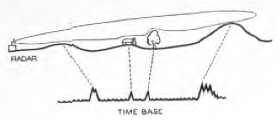
Figure 1. Clutter
Field radar equipments must be sited to remove as much clutter as possible from the time-base. This is done by “screening” the equipments—that is, the equipment is sited behind a low crest so that its lobe is just above those objects which would cause clutter (Fig 2).
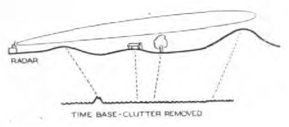
Figure 2. Screening
The use of screening is particularly important when radar equipments are used for the location of mortars, as locations are obtained from information of their projectiles in flight. Measurements of range, bearing, and angle of sight to individual projectiles are taken at selected points, or continuously as with aircraft targets (Fig 3).
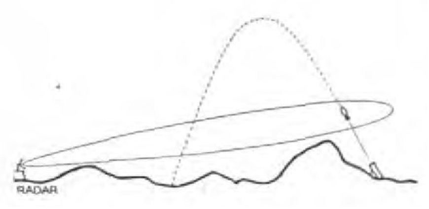
Figure 3. Location of Mortars
There are three stages in the process of location:—
(a) Initial detection while searching.
(b) Accurate observation.
(c) Deduction of the co-ordinates of the weapon.
The radar equipment is allotted an arc in which to search for suspected mortar positions. A PPI display is used initially —the aerial system, instead of rotating through 360 degrees, is set to move backwards and forwards across the search arc. This system of searching is known as “sector scan” and must be done at a rapid rate to ensure that the small, fast moving projectile is detected at as small an angle of sight as possible.
When a projectile is observed, the aerial system is laid on the bearing indicated on the PPI, and the accurate range measuring device of the equipment is set at the indicated range. The echo of the next projectile from the weapon should appear on the A-display at the set range.
Completion of the second stage of location—accurate observation—depends on the type of equipment in use. As the most accurate weapon-locating radar employs automatic following and an automatic information plotter, this method will be described.
When the second projectile is observed, the automatic following gear is switched on, and the projectile is followed throughout the visible portion of its trajectory. (That is, that portion of the trajectory above the screening angle Fig 3.)
Data is passed automatically and continuously to a plotter in the form of range, bearing, and height (the measured range and angle of sight being converted to height). At the plotter, range, bearing and height are plotted independently against time, and a reference line corresponding to the height of the radar position is also traced. An example of the type of plot is shown in Fig 4.
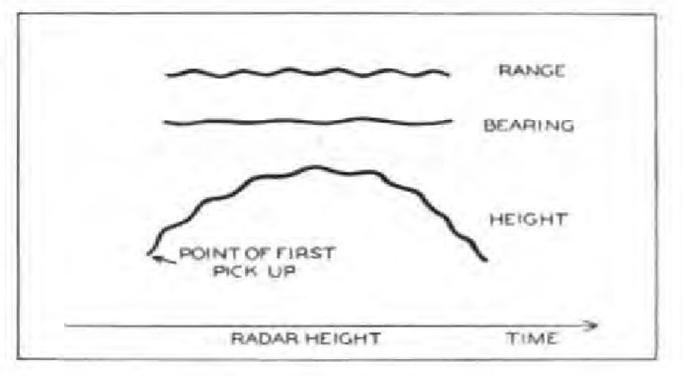
Figure 4. Data Plot
From this plot, the last stage of location is done — the deducing of co-ordinates. The curves of height plotted against time for all types of mortars and angles of departure approximately very closely to the parabola h = ½ gt2, when h = height, t = time, and g = the acceleration due to gravity. All height/time curves can therefore be smoothed and extrapolated by means of a single parabolic template cut to this formula.
The place where the smoothed, extrapolated height curve cuts the radar height line will be the time at which the mortar fired (Fig 5).
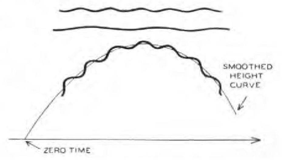
Figure 5. Extrapolated Height Curve
If the range and bearing plots are smoothed and extrapolated back to this time, then the range and bearing to the mortar position can be read off on suitable scales, (Fig 6.)
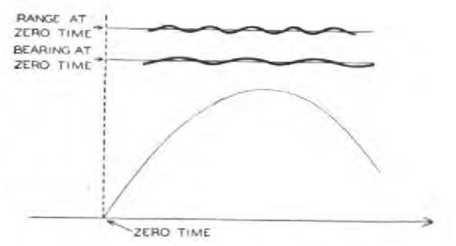
Figure 6. Extrapolation of Range and Bearing
A correction for any difference in height between radar equipment and mortar position must be made, and then the co-ordinates of the mortar position can be read from an artillery board.
The location of guns presents many unsolved problems. The method used for the location of mortars is applicable but with these differences :—
a. Projectiles have greater velocity.
b. The shape of shells is such that they give weak radar echoes.
c. Height/time curves of shell trajectories do not closely approximate to any particular curve as do mortars.
Observation of Fire
When a projectile explodes on the ground there is a rapid scattering of fragments and also of the debris, earth, etc., thrown up by the explosion. Using a radar equipment operating on a short wavelength (less than 10 centimetres) it is possible to obtain an echo from ground bursts. The size of the echo depends on the quantity and quality of debris thrown up. A large projectile with a delay fuze, bursting in soft wet soil produces the best echo, while the echo from a small shell, with an instantaneous fuze bursting on hard, dry ground may be too small to be detected.
The type of display fitted to radar equipments used for observation of fir is called a B-scope. This is a compromise between the A-scope and the PPI described previously. The time base moves vertically up the face of the CRT, echoes causing an increase in the brilliance of the spot. in addition, the time base is moved from side to side across the CRT in synchronism with a scanning aerial system. (Fig 7.)
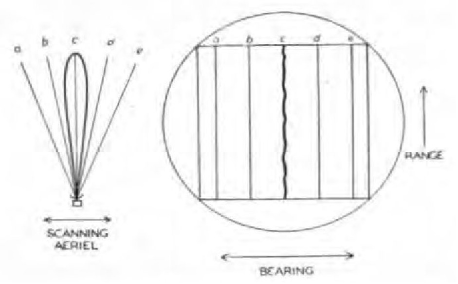
Figure 7. B-Scope
Vertical bearing graticules are engraved on the face of the CRT, and electrical range markers are provided. A target at 5250 yards at Right 10 degrees with respect to the radar equipment would produce an echo as shown in Fig 8.
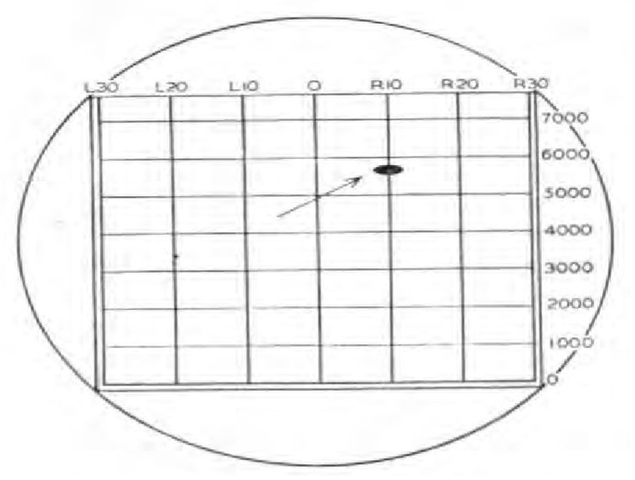
Figure 8. Target Display on B-Scope
The methods of correcting fire are as follows:—
(a) If the target to be engaged gives a target which is recognizable on the B-scope then the fall of shot is observed relative to the target and the necessary corrections ordered. While the general principles of ranging are unaltered, the process of bracketing is much reduced because radar will measure exactly how far each shot falls from the target.
(b) If the target gives no recognizable signal, but its co-ordinates are known, then the bearing and range from the radar are calculated and the aerial system is laid so that the target would appear on the centre graticule of the CRT. Fire is then corrected to the centre of the CRT.
Two conditions essential for operation are, one, a clear line of sight between radar aerial and burst, and two, clutter in the observed area must not be so strong as to obscure the echo from the bursts.
If these ground effects can be eliminated, observation becomes more certain and the siting of the radar equipment becomes an easier problem. Observation of airbursts, and tracking our own projectiles are two steps in this direction. Airbursts are observed in a similar manner to ground bursts, except that special shells are used. These contain “brads”—metal wire cut to half the wavelength of the radar equipment in use. The brads are scattered by the explosion of the shell and produce a strong echo. Projectiles are tracked by the same equipment used for mortar location, and information is obtained of points as far down the trajectories as possible.
In both cases, the correction of the moment is obtained from observation of a group of rounds, and map data to targets can be corrected.
Detection of Movement
It has been stated that, while the echoes of guns or mortars would be lost in the clutter caused by surrounding objects, moving targets could be detected. This detection is possible, even in heavy clutter, because of what is known as the “doppler effect.”
The frequency, or pitch, of the whistle from an approaching train differs from that of a stationary or receding one. This sound wave phenomenon is exactly the same in the case of radio waves, and is called the doppler effect. Radio waves reflected from a moving object are different in frequency from those reflected from a stationary object. When a moving object passes a stationary object, their echoes will merge together and the combined echo will rapidly vary in amplitude. This variation in amplitude is termed “beating,” and will indicate the presence of a moving target in clutter.
On an A-display, the effect is shown in Fig 9—the effect on a B-scope is that the signals show up as broken echoes producing a striated effect. (Fig 10.)
This same effect can be used to operate a loud speaker. The radar equipment is sited to watch a selected point—when a movement is detected, an aural signal is produced. This method obviates the necessity for operators to strain their eyes watching the CRT for long periods.
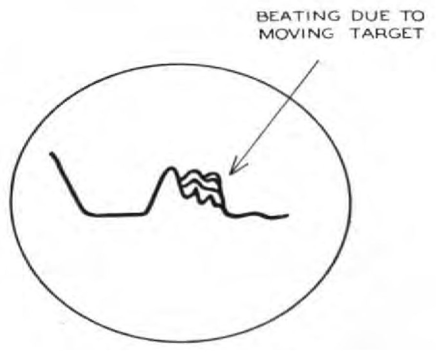
Figure 9. A Display Doppler
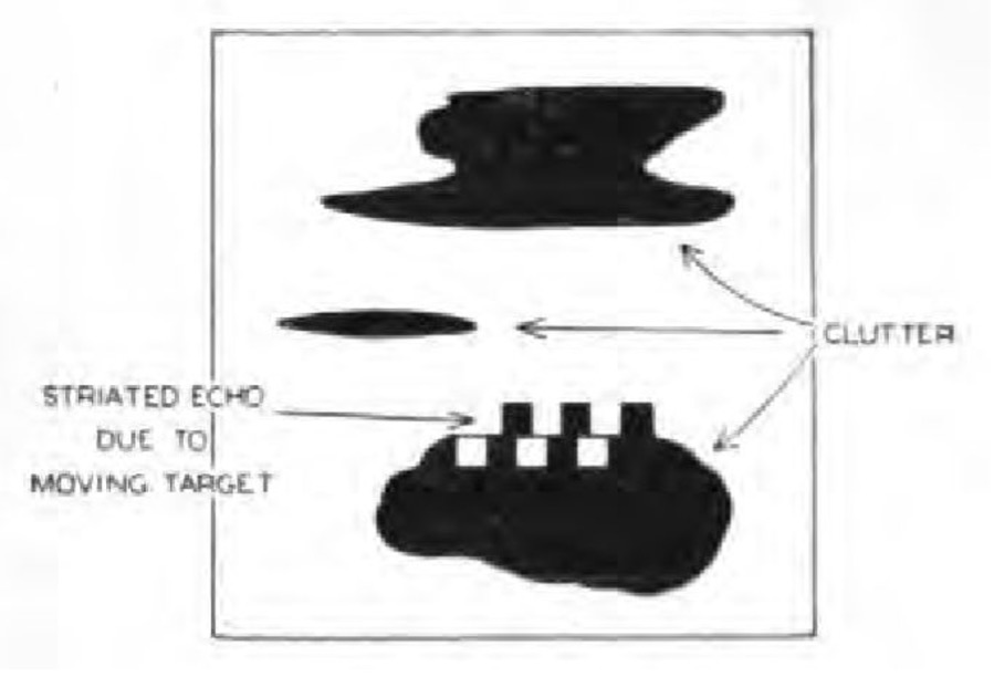
Figure 10. B Scope Doppler
The detection of movement by radar methods has three main uses:—
a. Intelligence—the equipment can indicate when movement is taking place at selected points.
b. Engagement of movement—using a B-scope, controlled harassing fire can be brought down on detected movement.
c. Control of watercraft—radar can be used to direct the movement of watercraft across lakes, or in coastal operations.
Radar Survey
Under certain conditions normal survey methods will be slow due to the absence of a clear line of sight. A method of using radar in “quick survey” has been devised to overcome this difficulty, and to put the guns of a division on a divisional grid quickly. The method uses airbursts as aerial reference objects.
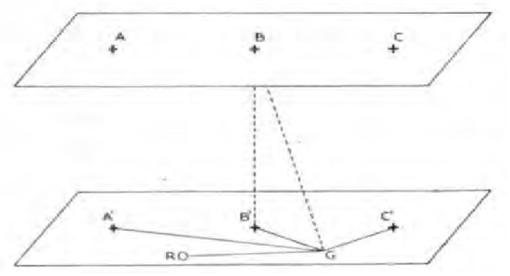
Figure 11. Radar Survey
The origin of the divisional grid is a radar equipment, which may be surveyed or given arbitrary co-ordinates. Rounds from a gun sited near the radar equipment, are fired to give airbursts at three points parallel to the FDLs and spaced apart about 3000 yards, and at about 8000 yards from the gun areas.
The radar station fixes the airbursts by movement of range by radar, and bearing and angle of sight by optical instruments. At each gun position, directors are used to record the angle from a reference object and the angle of sight to each airburst. A set drill ensures that all stations relate recorded data to specific airbursts.
The radar station records to each airburst the range, bearing, and angle of sight, and can compute the height of each burst and the co-ordinates of the point on the ground directly beneath each airburst. (Fig 11.)
This information is broadcast to all gun positions. Here the angles from the RO to the bursts A, B and C are drawn out on tracing paper. The co-ordinates of A1, B1 and C1 having been plotted on the artillery board, a tracing paper resection is carried out and the position of the gun position fixed at G. By computation, the range and bearing from G to say B1 can be calculated. Then the bearing to the RO can be adjusted to conform with the orientation with the radar station.
The difference in height between G and the airburst B, and hence the height of the gun position, can be calculated from the known height of B and the angle of sight to it as measured at the gun position.
The nature of the accuracy to be expected is 25 yards for fix, 10 minutes for orientation, and 25 feet for height, and the time taken is about one hour, irrespective of the number of gun positions to be fixed.
For the location of forward troops, reasonable accuracy can be obtained by radar observation of one mortar bomb fired from the troops.
With wireless communication between radar equipment and mortar position, a special mortar bomb is fired at a prearranged QE to give an airburst at a pre-arranged height. The radar then observes range and bearing to the burst —knowing the height of burst, and the bearing and QE at which the mortar was fired, the co-ordinates of the mortar position can be deduced.
Conclusion
From the foregoing paragraphs, it can be seen that the use of radar by field artillery falls into three divisions:—
a. The detection and location of the enemy and his weapons, either by direct observations, or by deductions from observations of enemy projectiles.
b. Control of fire, by observation of our own projectiles or bursts.
c. Other uses such as quick survey, location of forward troops, and direction of watercraft.
In each of these divisions, some applications have been tested in battle, others have been developed in peacetime, and others are yet in the stages of development. As far as the Australian Army is concerned, each application has to be learned as a new procedure. Until every artillery officer is conversant with radar principles and their applications, artillery units cannot provide the best available fire support for infantry and armoured troops.
Artificial Moonlight*
Lighting of combat areas by searchlight beams was first used by the British Eighth Army in Italy in September 1944. It was picked up by the U.S. Army and tried in Europe and the Pacific, and the Germans employed it early in 1945.
Artificial moonlight aids movement of vehicles, the servicing of artillery weapons, and patrolling or attacking infantry. It marks front-line boundaries for aircraft, speeds engineer road and bridge maintenance, and provides a means of signalling.
However, the beams often silhouette our own troops, permit enemy observation from flanks, cause possible loss of surprise, provide lighting of the enemy’s front area, and assist enemy airmen in strafing and bombing.
In employing searchlight in support of ground action, the terrain should be open and preferably sloping toward the enemy. Positions defiladed from the front and sides and hiding at least 100 yards of the beam are desirable.
A solid cloud base at 500 to 5,000 feet gives the maximum reflection. Tests are being made with 800 million-candle-power beams pointed at artificially-produced clouds and artillery smoke bursts. Ground haze, fog and rain cut the effectiveness, and wind prevents cloud stability. Ice or fallen snow increase visibility.
Best results were obtained between 3,000 and 7,000 yards. Visibility falls off sharply beyond 7,000 yards.—MILITARY REVIEW, U.S.A.
* A more detailed article on Artificial Moonlight in ATM 44.
